Necessary equipment
DW 110–060 Engine clamping fixture
EN-48245 Timing Belt Adjuster - Camshaft Holder
EN-48246 Timing Belt Adjuster - Crankshaft Holder
Removal procedure
1. Disconnect the negative battery cable.
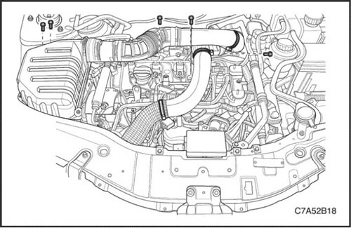
2. Remove the decorative cover. See "Decorative cover" in this section.
3. Remove the air intake hoses and ducts. See "Air injection system" in this section.
4. Remove the auxiliary belt. See "Accessory Drive Belt and Tensioner" in this section.
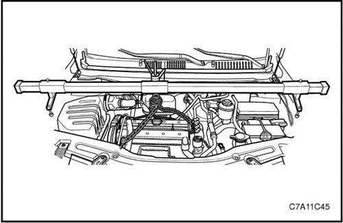
Caution: Raise the engine sufficiently to relieve the load on the engine mount, otherwise damage to the mount and failure of the lifting equipment may occur.
5. Support the engine assembly using the DW110-060 engine clamp.
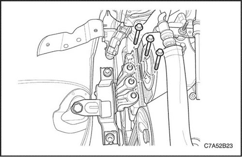
6. Remove the engine mount damper block. See "Engine mount assembly (right side)" in this section.
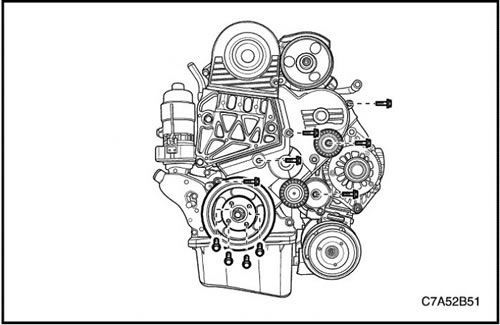
7. Remove the upper timing belt cover.
8. Remove the accessory drive belt tensioner roller.
9. Remove the tensioner. See "Accessory Drive Belt and Tensioner" in this section.
10. Remove the crankshaft pulley.
11. Remove the lower timing belt cover.
12. Remove the engine mount bracket.
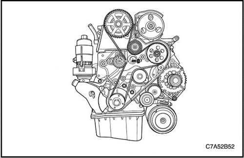
13. Remove the timing belt tensioner.
14. Remove the drive belt of the gas distribution mechanism.
15. Remove the camshaft sprocket.
Adjusting the tension of the timing belt
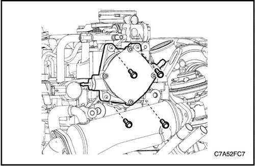
1. Remove the vacuum pump. See Section 1F1, Engine Controls - 2.0 Diesel.
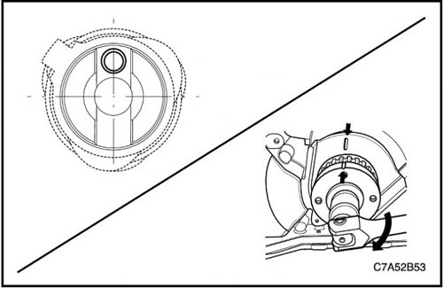
2. Rotate the camshaft to align it with the hole at the top point.
3. Rotate the crankshaft to align it with the mark on the crankshaft sprocket.
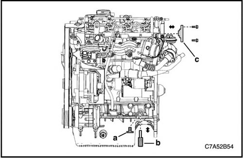
4. Loosen the plug bolt (a) of the hole for the crankshaft holder.
5. Insert the EN-48246 crankshaft holder into the hole (b) for the crankshaft holder.
Note: While rotating the crankshaft sprocket slightly, insert the crankshaft holder at the same time.
6. Install the EN-48245 camshaft holder to the rear side (c) of the camshaft.
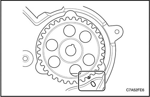
7. Align the mark on the sprocket with the mark on the rear timing belt cover.
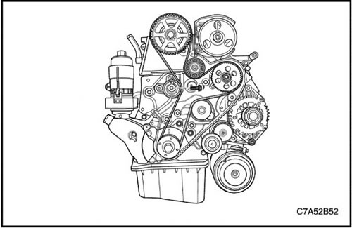
8. Install the camshaft sprocket and tighten the bolt by hand.
9. Install the timing belt of the gas distribution mechanism.
10. Install the timing belt tensioner by tightening the bolt by hand.
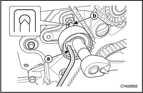
11. Turn the Allen key protrusion (a) counterclockwise to tighten the belt. Turn until the dot aligns with the notch (b).
12. After aligning with the notch, tighten the timing belt tensioner bolt.
13. Tighten the camshaft sprocket bolt.
Tighten
Tighten the timing belt tensioner bolt to 25 Nm (18.4 lbs.in).
Tighten the camshaft sprocket bolt to 133 N·m (98.1 lbs.in).
14. Remove the camshaft holder EN-48245 and crankshaft holder EN-48246.
15. Turn the crankshaft clockwise more than 2 cycles and check the mark on the crankshaft sprocket.
16. After aligning the timing belt, tighten the plug bolt for the hole for the crankshaft holder.
Tighten
Tighten the crankshaft holder hole plug bolt to 30 Nm (22.1 ft·lbs).
Note: If there is no alignment with the TDC point of cylinder No.1, repeat the above procedure for No.4 ~ No.10 until there is alignment.
Caution: Since the installation of these special service tools is aimed at aligning with the TDC point of cylinder #1, if the alignment is not precise, it will affect engine power and emissions.
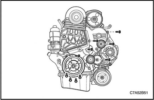
Installation procedure
1. Install the engine mount bracket.
2. Install the lower timing belt cover.
3. Install the crankshaft pulley.
4. Install the accessory drive belt tensioner roller.
5. Install the upper timing belt cover.
Tighten
Tighten the engine mount bracket bolts to 45 Nm (33.1 ft·lbs).
Tighten the lower timing belt cover bolts to 11 N·m (97.4 lbs.in).
Tighten the crankshaft pulley bolts to 34 Nm (25.1 ft·lbs).
Tighten the accessory drive belt tensioner roller bolt to 52 Nm (38.4 ft·lbs).
Tighten the upper timing belt cover bolts to 11 N·m (97.4 lbs.in).