


Contents: Features of the device ↧ Valve drive mechanism ↧ Hydraulic chain tensioner ↧ Removal and installation the… ↧ Disassembly and assembly of the… ↧ Technical condition check and repair ↧
Features of the device
The main dimensions of the valves, valve guides and seats are given in Figure 2-45.
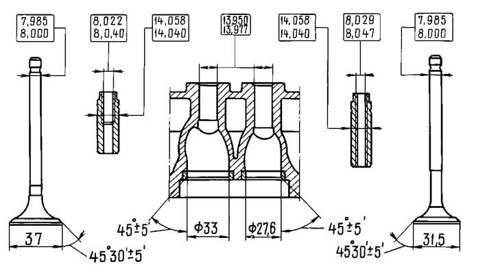
Figure 2-45. Basic dimensions of valves, valve guides and seats.
The cylinder head is cast from an aluminum alloy, has pressed-in cast-iron seats and valve guides. The upper part of the bushings is sealed with rubber-metal oil-deflecting caps.
Guide bushings are supplied as spare parts with an outer diameter increased by 0.2 mm.
The bearing housing, which contains the camshaft, is fixed to the cylinder head.
Valve drive mechanism
Valves 2 (figure 2-46) are driven by the camshaft cams through levers 3. One end of the lever presses on the valve, and the other rests on the spherical head of the hydraulic support 6. The hydraulic supports automatically eliminate the gap in the valve mechanism and therefore there is no need to check and adjust the gap in the valve mechanism during vehicle maintenance.
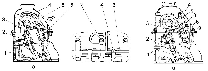
Figure 2-46. Valve drive mechanism:
1 - cylinder head;
2 - valve;
3 - valve lever;
4 - oil ramp;
5 - camshaft;
6 - hydraulic pusher support;
7 - nut;
8 - hydraulic support bushing;
9 - spacer.
Hydraulic chain tensioner
Oil from the lubrication system through pipe 3 (see figure 2-12) enters cavity "E" (figure 2-47) tensioner, then through hole "D" and valve unit 2 enters the working cavity "B" and presses on plunger 5. In the housing 1 of the tensioner there is a hole with a diameter of 1 mm for bleeding air from cavity "E".
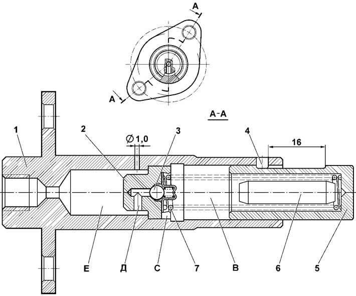
Figure 2-47. Hydraulic chain tensioner:
1 - tensioner housing;
2 - valve unit;
3 - check valve ball;
4 - limit pin;
5 - tensioner plunger;
6 - volume limiter;
7 - plunger spring;
B - working cavity;
C - installation groove;
D - hole;
E - reserve cavity.
The diametrical gap between body 1 and plunger 2 should be 0.018-0.024 mm and is measured as the difference between the maximum measured diameter of plunger 2 and the minimum measured diameter of body 1.
During repair, the tensioner housing and plunger form a pair, in which replacement of one part by the other after selection of the gap is not allowed. Plunger 2 must move in housing 1 without jamming by a stroke value equal to 16 mm.
When installed on the engine, the tensioner must be free of oil, pin 4 must not protrude from the housing.
Removal and installation the cylinder head on a car
The cylinder head is removed from the engine on the vehicle if the entire engine does not need to be disassembled to fix the problem. For example, if it is necessary to remove carbon deposits from the surface of the combustion chambers and valves or replace the valves or valve guides.
Remove the cylinder head in the following order:
- place the vehicle on a lift and relieve pressure in the fuel supply system. To do this, disconnect the electric fuel pump wiring harness connector from the ignition system wiring harness, start the engine, and let it run until it stops;
- disconnect the wire from the negative terminal of the battery;
- raise the vehicle and drain the coolant from the radiator and cylinder block, following the recommendations in the subsection "Removing and installing the engine";
- disconnect the muffler inlet pipe from the exhaust manifold, remove the coolant pump inlet pipe bracket;
- lower the car, disconnect the hose (see figure 2-4) fuel supply from the fuel pipe. Plug the openings of the hose and pipe to prevent dirt from getting into them;
- disconnect cable 2 (see figure 2-5) accelerator drive from the throttle pipe and from bracket 4 on the receiver;
- remove the crankcase ventilation hoses by disconnecting them from the pipes on the cylinder head cover, from the intake pipe hose and from the throttle pipe;
- loosen the clamps and disconnect hose 1 from the throttle pipe (see figure 2-6) intake pipe, purge hose of the adsorber, hoses of supply and discharge of the coolant;
- disconnect the vacuum hose from the receiver to the brake booster;
- disconnect the wires from the spark plugs, from the oil pressure indicator lamp and coolant temperature gauge sensors, from the throttle body; disconnect the wires from the injector wiring harness;
- disconnect the hoses from the engine cooling jacket outlet pipe;
- remove the cylinder head cover with gasket, engine screen brackets and accelerator cable;
- turn the crankshaft until the mark on the camshaft sprocket aligns with the mark on the bearing housing (see figure 2-26);
- unscrew the bolt securing the camshaft sprocket, unscrew the nipple, nuts and remove the hydraulic chain tensioner, remove the camshaft sprocket;
- unscrew the bolts securing the cylinder head to the block and remove the cylinder head with the gasket.
Install the cylinder head in the reverse order of removal, following the recommendations in the subsection "Engine Assembly". The gasket between the head and the cylinder block cannot be reused, so replace it with a new one.
After installing the cylinder head, adjust the accelerator drive.
Check the operation of the engine management system.
Disassembly and assembly of the cylinder head
Disassembly. If only one part needs to be replaced, then you don't have to disassemble the entire cylinder head and remove only what is needed for replacement.
Place the cylinder head on a stand, unscrew the nuts and remove the intake pipe, exhaust manifold and intake pipe screen. Remove the cooling jacket outlet pipe and the liquid outlet pipe to the heater. Unscrew the spark plugs and coolant temperature sensor.
Loosen the mounting nuts and remove the bearing housing together with the camshaft. Loosen the nuts securing the thrust flange to the bearing housing. Remove the flange and take the camshaft out of the bearing housing.
Remove the levers 3 (see figure 2-46) valves.
Unscrew the hydraulic supports 6 (see figure 2-46a) and remove the oil ramp 4.
On engines equipped with INA hydraulic bearings, remove the hydraulic bearings 6 (see figure 2-46b), unscrew the bushings 8 of the hydraulic supports, remove the oil ramp 4 with the spacers 8 as an assembly.
Install the cylinder head on tool 67.7823-9567, compress the valve springs and release the crackers.
Remove the valve springs with the plates and support washers. Turn the cylinder head and remove the valves from the bottom. Remove the oil-deflecting caps from the guide bushings.
Assembly. Assemble the cylinder head in the reverse order of disassembly. Lubricate the valves and valve stem seals with engine oil before assembly.
Before installing the camshaft bearing housing, check that the mounting bushings are in place (see figure 2-25). Tighten the bearing housing fastening nuts in the order shown in Figure 2-27. In doing so, make sure that the mounting bushings enter the bearing housing sockets without skewing.
Before installing hydraulic mounts from spare parts, place each hydraulic mount in a container with engine oil until it is completely immersed in oil and press several times with your hands until the plunger free play is removed.
Technical condition check and repair
Cylinder head. Wash the cylinder head thoroughly and clean the oil passages. Remove carbon deposits from the combustion chambers and from the surface of the exhaust passages with a wire brush.
Inspect the cylinder head. Cracks in any place of the cylinder head are not allowed. If you suspect that coolant has entered the oil, check the tightness of the cylinder head.
To check for leaks, close the openings of the cylinder head cooling jacket with the plugs included in the A.60334 tool kit (figure 2-48). Supply compressed air at a pressure of 0.15-0.2 MPa into the head (1.5-2 kgf/cm). Within 1-1.5 minutes, no air bubbles should be observed escaping from the head.
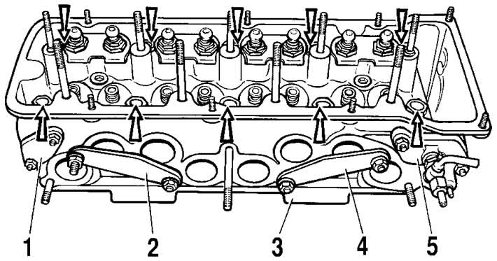
Figure 2-48. Checking the cylinder head tightness using the A.60334 device:
1, 2, 4 - plugs;
3 - fixture plate;
5 - flange with air supply nipple.
Valve seats. The shape of the valve seat chamfers is shown in Figures 2-49 and 2-50. On the working chamfers of the seats (valve contact area) there should be no pitting, corrosion or damage. Minor damage can be eliminated by grinding the seats, removing as little metal as possible. Grinding can be done either manually or with a grinding machine.
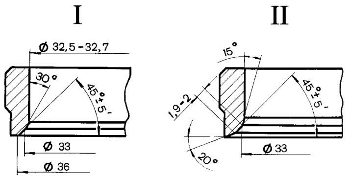
Figure 2-49. Intake valve seat profile:
I - new saddle;
II - saddle after repair.
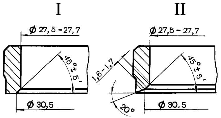
Figure 2-50. Exhaust valve seat profile:
I - new saddle;
II - saddle after repair
To grind the seats, place the cylinder head on a stand, insert the rod A.94059 into the valve guide sleeve and clean the seat chamfers from carbon deposits using countersinks A.94031 and A.94092 for exhaust valve seats and countersinks A.94003 and A.94101 for intake valve seats. The countersinks are placed on the spindle A.94058 and centered using the guide rod A.94059. These rods are available in two different diameters: A.94059/1 for intake valve guide sleeves and A.94059/2 for exhaust valve guide sleeves.
Place spring A.94069/5 on guide rod A.94059, install conical circle A.94078 for exhaust valve seats or circle A.94100 for intake valve seats on spindle A.94069, secure spindle in grinder and grind valve seat (figure 2-51).
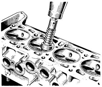
Figure 2-51. Grinding the working chamfer of the valve seat.
At the moment of contact of the wheel with the saddle the machine should be switched off, otherwise vibration will occur and the chamfer will be incorrect. It is recommended to correct the wheel with a diamond more often.
For the exhaust valve seats, bring the working chamfer width to the values shown in Figure 2-51 using countersink A.94031 (angle 20°) and countersink A.94092, which removes work hardening on the inner diameter. Countersinks are placed on spindle A.94058 and, as with grinding, are centered using rod A.94059.
At the inlet valve seats, bring the width of the working chamfer to the values shown in Figure 2-52, first processing the inner chamfer with a countersink A.94003 (figure 2-52) until a diameter of 33 mm is obtained, and then a 20° chamfer with a countersink A.94101 until a working chamfer of 1.9-2 mm width is obtained.
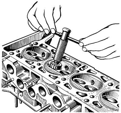
Figure 2-52. Narrowing the working chamfer of the valve seat using a countersink mounted on spindle A.94058.
Valves. Remove carbon deposits from the valves. Check that the stem is not deformed and that there are no cracks on the plate. Replace the damaged valve.
Check the condition of the valve working chamfer. In case of minor damage, it can be ground, maintaining the chamfer angle of 45°30'±5'. In this case, the distances from the lower plane of the valve plate to the base diameters (36 and 30.5 mm) must be within the limits shown in Figure 2-53.
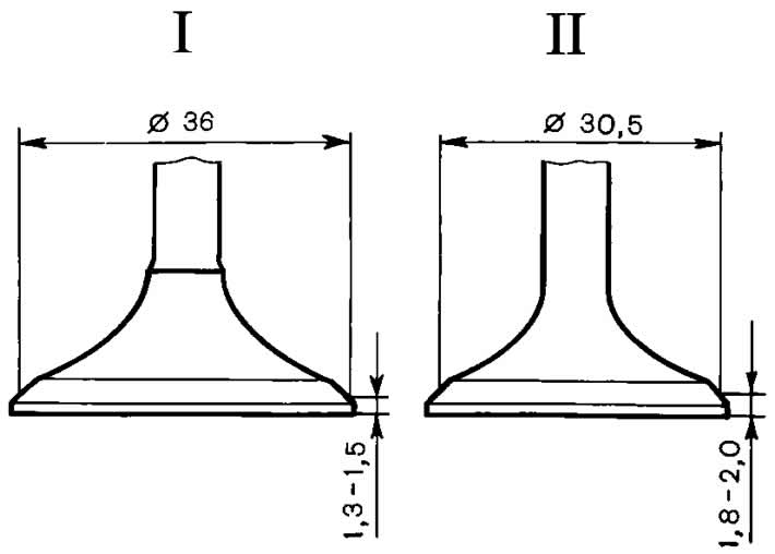
Figure 2-53. Limit dimensions for grinding valve chamfers:
I - inlet valve;
II - exhaust valve.
Valve guides. Check the clearance between the guides and the valve stem by measuring the valve stem diameter and the guide bore.
Calculated clearance for new bushings: 0.022-0.055 mm for intake valves and 0.029-0.062 mm for exhaust valves; maximum permissible marginal clearance (when worn out) — 0.3 mm, provided that there is no increased noise from the valve timing mechanism.
If the increased clearance between the guide bushing and the valve cannot be eliminated by replacing the valve, then replace the valve bushings using the A.60153/R mandrel for pressing out and pressing in (figure 2-54).
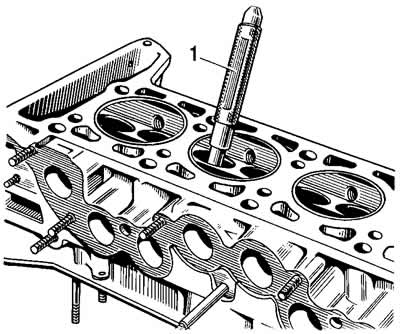
Figure 2-54. Pressing out guide bushings:
1 - mandrel A.60153/R.
Press in the guide bushings with the retaining ring fitted until it rests against the cylinder head body.
After pressing, ream the holes in the guide bushings using A.90310/1 reamers (for intake valve bushings) and A.90310/2 (for exhaust valve bushings).
Always replace the guide bushing oil caps with new ones when repairing the engine.
Replace damaged oil seals on the removed cylinder head. Use mandrel 41.7853.4016 to press in the seals.
Springs. Make sure that the springs are not cracked or have lost their elasticity by checking their deformation under load (figure 2-55).
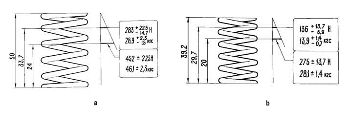
Figure 2-55. Basic data for checking the outer (a) and inner (b) valve spring.
Cylinder head mounting bolts. When using bolts repeatedly, they stretch out. Therefore, check that the length of the bolt shaft does not exceed (excluding head length) 117 mm and if it is more, then replace the bolt with a new one.
Hydraulic bearings. Check the condition of the hydraulic bearings. The plunger of the hydraulic bearing installed in the cylinder head should not move when pressed sharply by hand. If the plunger moves freely, replace the hydraulic bearing.
Valve levers. Check the condition of the working surfaces of the lever that mate with the valve stem, the camshaft cam and the spherical end of the hydraulic support plunger. If these surfaces have scoring or scratches, replace the lever with a new one.