


Features of the device
The main dimensions of the crankshaft are given in Figure 2-41.
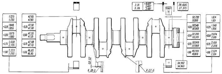
Figure 2-41. Main dimensions of the crankshaft.
The crankshaft is cast iron, five-bearing. It is possible to regrind the crankshaft journals during repairs with a diameter reduction of 0.25; 0,5; 0,75; and 1 mm.
The axial movement of the crankshaft is limited by two thrust half rings. They are inserted into the cylinder block sockets on both sides of the fifth main bearing, with a metal-ceramic half ring (yellow) installed on the rear side and a steel-aluminum half ring on the front side. The half rings are made in two sizes - normal and increased in thickness by 0.127 mm.
The crankshaft bearing shells are thin-walled, steel-aluminum. The upper shells of the 1st, 2nd, 4th and 5th crankshaft bearings have a groove on the inner surface, and the lower shells do not have a groove. The shells of the 3rd bearing (upper and lower) without groove. Connecting rod bearings (upper and lower) also without a groove.
Repair liners are made with increased thickness for crankshaft journals, reduced by 0.25; 0,5; 0.75 and 1 mm.
The flywheel is cast iron, with a pressed-on steel toothed rim for starting the engine with a starter. The flywheel is centered by the front bearing of the gearbox drive shaft, pressed into the crankshaft.
On the rear plane of the flywheel near the toothed rim there is a setting mark in the form of a conical hole. It should be located opposite the connecting rod journal of the fourth cylinder.
Technical condition check and repair
Crankshaft. Inspect the crankshaft. Cracks anywhere on the crankshaft are not allowed. No scratches, nicks or grooves are allowed on the surfaces mating with the working edges of the seals.
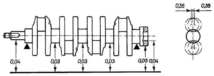
Figure 2-42. Permissible runout of the main surfaces of the crankshaft.
Install the crankshaft with the outer main journals on two prisms (figure 2-42) and check the runout with an indicator:
- root necks (no more than 0.03 mm);
- landing surfaces for the sprocket and bearing of the drive shaft of the gearbox (no more than 0.04 mm);
- surfaces mating with the seal (no more than 0.05 mm).
Measure the diameters of the main and connecting rod journals. The journals should be ground if their wear is more than 0.03 mm or the ovality of the journals is more than 0.03 mm, and also if there are burrs and scratches on the journals.
Grind the journals down to the nearest repair size (see figure 241).
When grinding, maintain the dimensions of the journal fillets similar to those shown in Figure 241 for normal crankshaft dimensions. The ovality and taper of the main and connecting rod journals after grinding should be no more than 0.005 mm.
The offset of the axes of the connecting rod journals from the plane passing through the axes of the connecting rod and main journals after grinding should be within ±0.35 mm (see figure 2-42). To check, install the shaft with the outer main journals on the prisms and adjust the shaft so that the axis of the crankpin of the first cylinder is in the horizontal plane passing through the axes of the main journals. Then use an indicator to check the vertical displacement of the crankpins of the 2nd, 3rd and 4th cylinders relative to the crankpin of the 1st cylinder.
After grinding the journals, polish them using diamond paste or GOI paste.
After grinding and subsequent finishing of the journals, remove the oil channel plugs and then process the plug seats with the A.94016/10 cutter mounted on the A.94016 spindle. Thoroughly wash the crankshaft and its channels to remove any remaining abrasive and blow them out with compressed air. Press in new plugs with a process rod and mark each one at three points with a center punch.
On the first cheek of the crankshaft, mark the amount of reduction of the main and connecting rod journals (for example, K 0.25; W 0.50).
Liners. No adjustment operations should be performed on the liners. In case of scoring, scratches, or delamination, replace the liners with new ones.
The clearance between the liners and the crankshaft journals is checked by calculation (having measured the parts). It is convenient to use a calibrated plastic wire to check the gap. In this case, the checking method is as follows:
- thoroughly clean the working surfaces of the liners and the corresponding neck and place a piece of plastic wire on its surface;
- install the connecting rod with the cap or the main bearing cap on the journal (depending on the type of cervix being checked) and tighten the nuts or bolts. Tighten the connecting rod bolt nuts to 51 Nm (5.2 kgf·m) and the main bearing cap bolts to 80.4 Nm (8.2 kgf·m);
- remove the lid and use the scale on the packaging to determine the size of the gap by flattening the wire (figure 2-43).
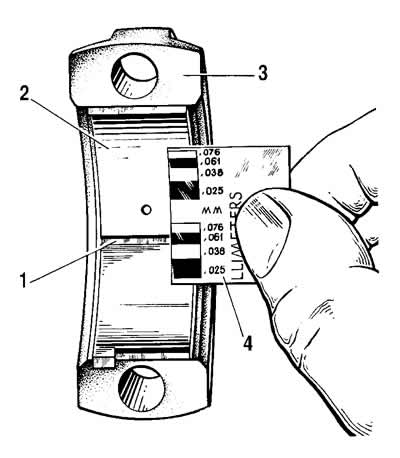
Figure 2-43. Measuring the clearance in the connecting rod bearing:
1 - flattened calibrated plastic wire;
2 - insert;
3 - connecting rod cover;
4 - scale for measuring the gap.
The nominal calculated clearance is 0.02-0.07 mm for connecting rod journals and 0.026-0.073 mm for main journals. If the clearance is less than the maximum (0.1 mm for connecting rod journals and 0.15 mm for main journals), then you can use these inserts again.
If the gap is greater than the maximum, replace the bearing shells on these journals with new ones.
If the crankshaft journals are worn and ground to a repair size, then replace the liners with repair ones (increased thickness).
Thrust half rings. Just like on the liners, no adjustment operations can be performed on the half rings. In case of scoring, scratches or delamination, replace the half rings with new ones.
The half rings are also replaced if the axial clearance of the crankshaft exceeds the maximum permissible value of 0.35 mm. Select new half rings of the nominal thickness or increased by 0.127 mm to obtain an axial clearance within 0.06-0.26 mm.
The crankshaft axial clearance is checked using an indicator as described in the subsection "Engine assembly" (see figure 2-19).
The axial clearance of the crankshaft can also be checked on the engine installed in the vehicle. In this case, the axial movement of the crankshaft is created by pressing and releasing the clutch pedal, and the clearance value is determined by the movement of the front end of the crankshaft.
Flywheel. Check the condition of the toothed rim and replace the flywheel if the teeth are damaged. If the flywheel has tarnished colors on the surface 3 (figure 2-44), it is necessary to check the tension of the rim on the flywheel. The rim should not turn at a torque of 590 Nm (60 kgf·m).
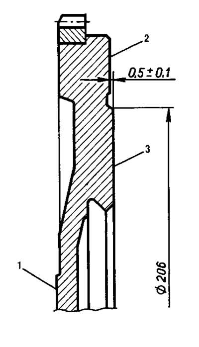
Figure 2-44. Flywheel:
1 - mounting surface to the crankshaft flange;
2 - clutch mounting surface;
3 - supporting surface of the driven clutch disc.
On surface 1 of the flywheel adjacent to the crankshaft flange and on surface 3 under the driven clutch disc, scratches and burrs are not allowed.
Remove scratches and burrs on surface 3 by turning, removing a metal layer no more than 1 mm thick. At the same time, also turn surface 2, maintaining the size of (0.5±0.1) mm. When turning, it is necessary to ensure the parallelism of surfaces 2 and 3 relative to surface 1. The tolerance for non-parallelism is 0.1 mm.
Mount the flywheel on the mandrel, centering it on the mounting hole with an emphasis on surface 1, and check the runout of planes 2 and 3. At the extreme points, the indicator should not show runouts exceeding 0.1 mm.
The article is based on data from the website: «ChevyMan»