
Place a clean block on the stand and screw the missing studs into it.
Lubricate the bearing shells and thrust half rings of the crankshaft, as well as the pistons and seals with engine oil. When assembling the engine after repair, install new crankshaft seals.
Place liners without a groove on the inner surface in the middle bearing seat and in its cover. Place liners with a groove in the remaining cylinder block seats, and liners without a groove in the corresponding covers.
Place the crankshaft in the main bearings and insert two thrust half rings into the rear support sockets (figure 2-17).
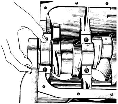
Figure 2-17. Installing thrust half rings on the rear support.
Warning: The half rings must be facing the grooves towards the thrust surfaces of the crankshaft (an antifriction layer is applied to the surface of the half ring from the groove side).
On the front side of the rear support, place a steel-aluminum half-ring, and on the rear side, a metal-ceramic one (yellow color).
Install the main bearing caps in accordance with the marks on their outer surface (figure 2-18). Tighten the cover mounting bolts.
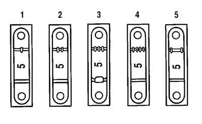
Figure 2-18. Marks on main bearing caps (the bearing count is from the front of the engine).
Check the axial free play of the crankshaft. To do this, install the indicator on a magnetic stand and insert the ends of two screwdrivers, as shown in Figure 2-19. While moving the shaft with the screwdrivers, measure the axial free play of the shaft with the indicator. It should be within 0.06-0.26 mm. If the free play is greater, then bring it back to normal by replacing the old half rings with new ones or installing half rings of increased thickness.
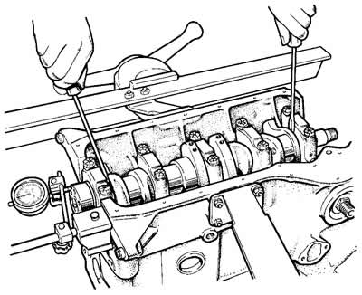
Figure 2-19. Checking the axial free play of the crankshaft.
Install the rear oil seal holder gasket onto the crankshaft flange and into the holder sockets (figure 2-20) insert the bolts securing the front cover of the clutch housing. Install the holder with the seal on the crankshaft flange, attach it to the cylinder block.
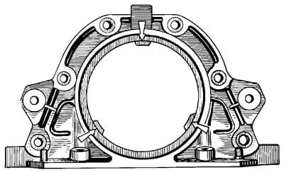
Figure 2-20. Crankshaft rear oil seal retainer. The arrows indicate the projections for centering the retainer relative to the crankshaft flange.
Install on two centering bushings (figure 2-21) front cover 6 (see figure 2-11) clutch housing. Attach the cover with nuts to the rear oil seal holder.
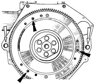
Figure 2-21. Clutch dowel pins (black arrows) and centering bushings of the clutch housing (white arrows).
Install the flywheel on the crankshaft so that the mark (cone-shaped hole) near the rim was opposite the axis of the connecting rod journal of the fourth cylinder, lock the flywheel with the A.60330/R lock and attach it with bolts to the crankshaft flange.
Using a piston ring crimper, insert the pistons with connecting rods into the cylinders (figure 2-22).
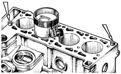
Figure 2-22. Installing the piston with piston rings using a ring crimping sleeve and cylinder head centering sleeves (shown by arrows).
Warning: The piston pin hole is offset from the axis by 1.2 mm, so when installing the pistons in the cylinders, the arrow on the piston bottom must point towards the camshaft drive.
Install the connecting rod liners and connecting rod caps. Install the connecting rods and caps onto the crankshaft journals and tighten the connecting rod bolts. The connecting rod caps must be installed so that the cylinder number on the cap is opposite the cylinder number on the lower connecting rod head.
Install the sprocket onto the crankshaft. Install the oil pump drive shaft and secure with the thrust flange.
Install two centering sleeves into the cylinder block (see figure 2-22) and install the cylinder head gasket on them.
Warning: Always install a new cylinder head gasket when reassembling the engine. Do not use a used gasket.
Before installing the gasket, remove all oil from the mating surfaces of the block and cylinder head. The gasket must be clean and dry. Do not allow oil to get on the gasket surface. If oil gets on the gasket, degrease it.
Turn the crankshaft so that the pistons are in the middle of the cylinders.
Install the cylinder head assembly with valves on the block using two centering bushings.
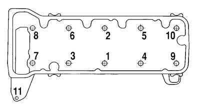
Figure 2-23. Cylinder head bolt tightening sequence.
Tighten the cylinder head bolts in the sequence shown in Figure 2-23. To ensure a good seal and to prevent the bolts from being overtightened during vehicle maintenance, tighten the cylinder head bolts in four stages:
- Step 1 - tighten bolts 1-10 to 20 Nm (2 kgf·m);
- Step 2 - tighten bolts 1-10 to 69.4-85.7 Nm (7.1-8.7 kgf·m), and bolt 11 to 31.36-39.1 Nm (3.2-3.99 kgf·m);
- Step 3 - tighten bolts 1-10 by 90°;
- Step 4: Tighten bolts 1-10 by 90° again.
Warning: Cylinder head bolts may only be reused if the bolt shaft has been extended to no more than 117 mm. If the bolt is longer, replace it with a new one.
Before assembling the engine, lubricate the threads and bolt heads in advance by dipping them in engine oil. Then let the excess oil drain off, keeping the bolts for at least 30 minutes. Remove oil from the bolt holes in the cylinder block.
Turn the flywheel to a position where the mark on the crankshaft sprocket aligns with the mark on the cylinder block (figure 2-24).
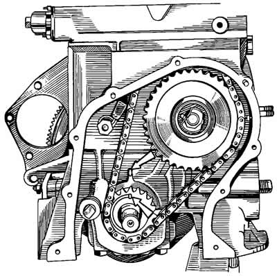
Figure 2-24. Checking the alignment of the timing mark on the crankshaft sprocket with the mark on the cylinder block.
Check that the camshaft bearing housing mounting bushings are in place (figure 2-25). Install the sprocket on the camshaft assembled with the bearing housing and turn the shaft so that the mark on the sprocket is opposite the mark on the bearing housing (figure 2-26). Remove the sprocket and, without changing the position of the shaft, install the bearing housing on the cylinder head so that the mounting bushings enter the bearing housing seats. Secure the bearing housing by tightening the nuts in the sequence shown in Figure 2-27.
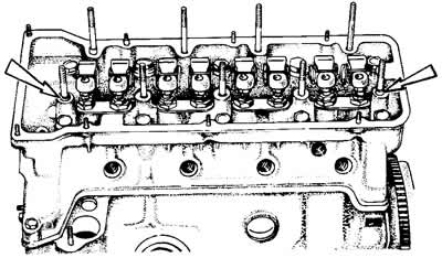
Figure 2-25. Mounting bushings for the camshaft bearing housing.
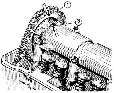
Figure 2-26. Checking the alignment of the timing mark on the camshaft sprocket with the mark on the bearing housing:
1 - mark on the sprocket;
2 - mark on the bearing housing.
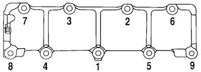
Figure 2-27. Camshaft bearing housing nut tightening sequence.
Install the chain guide on the cylinder head.
Install the camshaft timing chain:
- place the chain on the camshaft sprocket and insert it into the drive cavity, installing the sprocket so that the mark on it coincides with the mark on the bearing housing (see figure 2-26). Do not tighten the sprocket bolt all the way;
- install the sprocket on the oil pump drive shaft, also without completely tightening the mounting bolt;
- install the chain tensioner shoe and hydraulic tensioner;
- install the hydraulic tensioner tube;
- check that the marks on the sprockets match the marks on the cylinder block and on the bearing housing (see Figure 2-24 and 2-26);
- if the marks match, then lock the flywheel with the A.60330/R lock (see figure 2-9), finally tighten the sprocket bolts, bend back the sprocket bolt lock washers; if the marks do not match, repeat the chain installation operation.
Install the camshaft drive cover (figure 2-28) with the gasket and seal on the cylinder block, without finally tightening the bolts and nuts of the fastening. Center the position of the cover relative to the end of the crankshaft and finally tighten the nuts and bolts of its fastening.
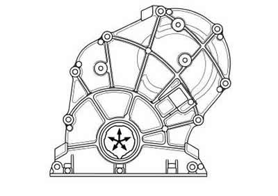
Figure 2-28. Camshaft drive cover. The arrows indicate the projections for centering the cover relative to the crankshaft pulley hub.
Install the crankshaft damper and secure it with the nut.
Install the power steering pump bracket with the pump assembly.
Install the oil filter with the gasket, hand-tightening it to the fitting on the cylinder block. Install the crankcase ventilation oil separator, breather cover and secure the oil separator drain pipe retainer.
Install oil pump 1 (figure 2-29) and an oil pan with a gasket.
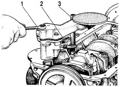
Figure 2-29. Installing the oil pump:
1 - oil pump;
2 - drain pipe retainer;
3 - oil separator drain pipe.
Install the coolant pump, alternator bracket and alternator. Install the belt on the pulleys and adjust its tension following the recommendations in the subsection "Adjusting the tension of the auxiliary drive belt".
Install the air conditioning compressor and its drive belt on the engine following the recommendations set out in the subsection "Air conditioning system".
Install the heater radiator inlet pipe and outlet pipe onto the cylinder head.
Install the exhaust manifold 2 onto the cylinder head (figure 2-9), screen 6 and inlet pipe 1.
Install the starter shield on the engine.
Install control instrument sensors.
Install the oil pump drive gear and gear retainer. Install the spark plugs and tighten them with a torque wrench.
Install the cylinder head cover with gasket, engine screen brackets and accelerator cable.
Install the ignition coil and knock sensor.
Install the fuel rail onto the intake pipe and secure it with bolts 3 (see figure 2-8). Connect the wiring harness to the injectors. Before installing the fuel rail, lubricate the injector sealing rings with engine oil.
Connect the fuel supply pipe to the rail.
Install the gasket on the intake pipe, receiver 6 (see figure 2-6), engine screen bracket and tighten the five nuts.
Attach the throttle pipe with the gasket to the receiver.
Connect the coolant supply and outlet hoses and the crankcase ventilation hose to the throttle body.
Fill the engine with engine oil through the filler neck on the cylinder head cover.
(The original article is on the website «chevyman.ru»)