


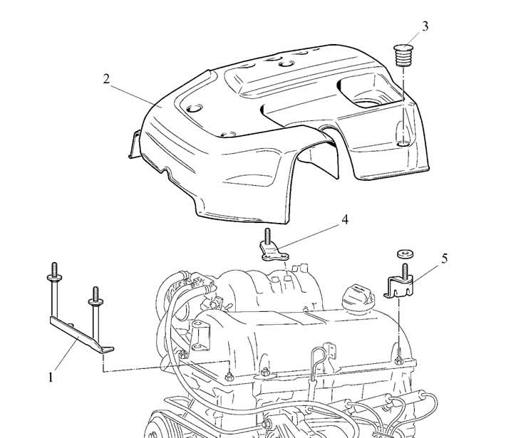
Figure 2-3. Removing the engine screen:
1 - front bracket;
2 - engine screen;
3 - screen mounting support;
4 - right bracket;
5 - rear bracket.
Remove the air filter:
- loosen the clamp securing the intake pipe hose to the spacer and disconnect the hose from the spacer;
- disconnect the wiring harness connector from the mass air flow sensor;
- unscrew the four bolts securing the front and rear air filter brackets to the vehicle body and remove the air filter with the mass air flow sensor and intake pipe hose assembly.
Drain the coolant from the radiator, cylinder block and heater, for which move the heater valve control lever to the right, unscrew the plugs on the left side of the cylinder block and on the right radiator tank, screw in the drain hose fittings instead and remove the plug from the expansion tank.
Loosen the mounting clamps and disconnect the coolant supply and return hoses from the radiator and from the engine.
Disconnect the expansion tank hose from the radiator.
Remove the radiator grille of the cooling system.
Disconnect the connector from the audio device and remove the audio device.
Remove the air conditioner condenser according to the requirements of the section "Ventilation, air conditioning and heating of the passenger compartment".
Disconnect the ignition system harness connectors from the fans.
Unscrew four bolts and remove covers 10 and 12 of radiator 11.
Unscrew the two bolts, remove the brackets 9 and remove the engine cooling system radiator complete with fans.
Disconnect the electrical equipment wires:
- disconnect the battery harness terminal from the generator;
- disconnect the "ground" wire from the engine;
- disconnect the ignition system wiring harness plug connectors from the injector wiring harness, ignition coil, oxygen sensor, temperature sensor, knock sensor, idle air control valve, throttle position sensor and crankshaft position sensor;
- disconnect the wire plugs from the coolant temperature gauge and oil pressure sensors.
Disconnect the vacuum hose from the receiver to the brake booster.
Disconnect the purge hose from the throttle body.
Loosen the mounting clamps and disconnect the heater radiator inlet and outlet hoses from the engine.
Disconnect the discharge line and low pressure line from the compressor.
Disconnect hoses 10 and 11 (figure 2-4-a) from fuel pipes 5 and 6 respectively or hose 2 (figure 2-4-b) from the fuel line. Install technological plugs in the openings of the hoses and lines to prevent dust particles from entering the air.
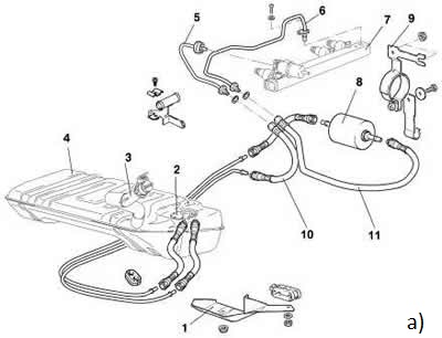

Figure 2-4. Fuel equipment parts:
a) for ECU with MP7.0 controller:
1 - bracket;
2 - electric fuel pump;
3 - filling pipe;
4 - fuel tank assembly;
5 - fuel outlet pipe;
6 - fuel supply pipe;
7 - fuel rail;
8 - fuel filter;
9 - fuel filter mounting bracket;
10 - outlet hose;
11 - supply hose.
b) for ECU with controller M7.9.7:
1 - fuel tank assembly;
2 - fuel line hose;
3 - fuel rail;
4 - electric fuel pump;
5 - fuel filter and fuel line tube;
6 - fuel filter;
7 - electric fuel pump and fuel filter tube.
Disconnect cable 2 (figure 2-5) accelerator drive from sector 1 on the throttle pipe, from bracket 4 on the receiver and from the brackets on the cylinder head cover.
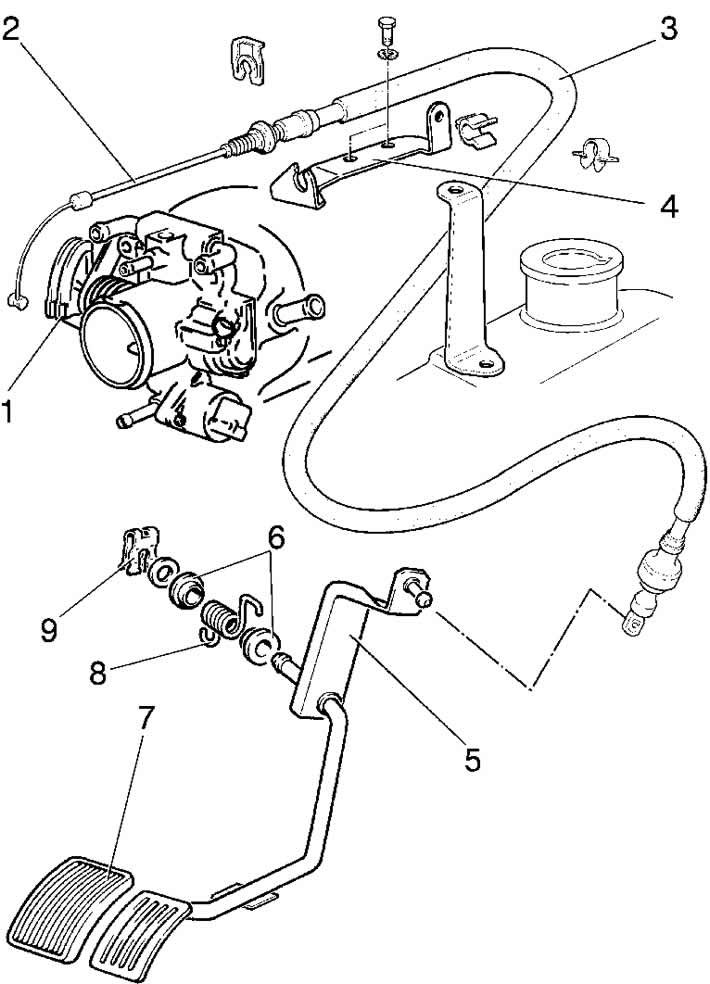
Figure 2-5. Removing the accelerator drive:
1 - sector with throttle control lever;
2 - throttle control cable;
3 - cable braiding;
4 - bracket;
5 - throttle control pedal;
6 - spring cups;
7 - pedal pad;
8 - spring;
9 - retainer.
Loosen the three clamps, unscrew the bolt securing the spacer to the cylinder head cover and remove hoses 1 and 4 (figure 2-6) intake pipe assembly, disconnecting them from throttle pipe 6, mass air flow sensor 9 and engine crankcase ventilation hose 3.
Loosen the bolts securing the air filter brackets to the vehicle body and remove the air filter 10 together with the mass air flow sensor 9, with the brackets and the air intake.
Disconnect the brake booster hose 8 from the receiver.
Disconnect the purge hose from the throttle body.
Drain the oil from the power steering reservoir. Disconnect the supply hose and high-pressure hose from the power steering pump and plug them.
Loosen the nuts securing the exhaust pipe to the exhaust manifold. Disconnect the exhaust pipe from the bracket on the gearbox and lower it down.
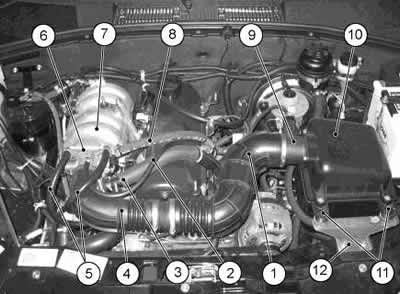
Figure 2-6. Removing air supply system components and parts:
1 and 4 - intake pipe hoses;
2 - crankcase ventilation tube;
3 - crankcase ventilation hose;
5 - throttle body heating hoses;
6 - throttle pipe;
7 - receiver;
8 - vacuum booster hose;
9 - mass air flow sensor;
10 - air filter;
11 - Air filter support;
12 - bracket.
Using a socket wrench, loosen the bolts securing the starter to the clutch housing, disconnect the wires from the starter and remove the starter. Loosen the bolts securing the clutch housing cover to the bottom of the clutch housing. Using a socket wrench, loosen the bolts securing the clutch housing to the cylinder block.
Install the 67.7820-9550 hydraulic crossbar on a hoist or crane and insert the hooks of the lifting device into the eye of the lifting eye on the right side of the engine, installed on the front exhaust manifold mounting stud, and behind the clutch housing mounting hole on the left side.
Lightly tighten the hoist chain, unscrew the nuts 7 (figure 2-7) fastening the 8 front engine mount cushions to the side brackets.
Place a transmission jack under the gearbox.
Remove the engine from the engine bay by first lifting it up to clear the suspension mount bolts from the bracket holes, then moving it forward to clear the end of the transmission input shaft from the bearing in the crankshaft flange. Remove the clutch mounting bolts and remove the clutch.
Install the engine on the vehicle in the reverse order of removal. When installing the clutch, use the A.70081 mandrel to center the driven clutch disc.
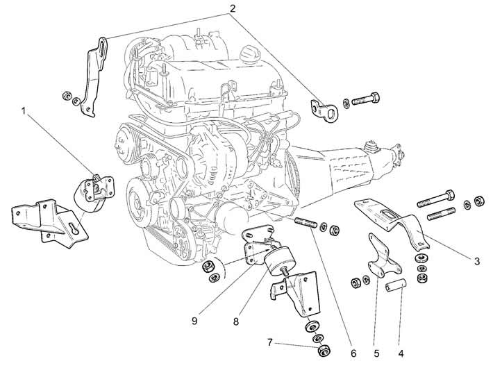
Figure 2-7. Removing the power unit:
1 - right engine mount bracket with cushion;
2 - eyes for slinging;
3 - rear engine mount cross member;
4 - spacer sleeve;
5 - rear engine mount support;
6 - hairpin;
7 - nut;
8 - pillow;
9 - left engine mount bracket.