


Features of the device
The main dimensions of the cylinder block are given in Figure 2-30.
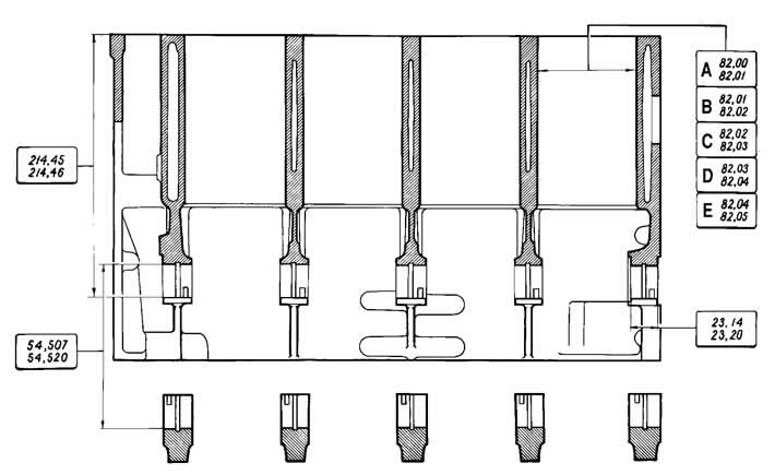
Figure 2-30. Main dimensions of the cylinder block.
The cylinder block is cast from special low-alloy cast iron. The cylinder diameters are divided into five classes through 0.01 mm, designated by the letters A, B, C, D, E. The cylinder class is stamped on the lower plane of the cylinder block (figure 2-31).
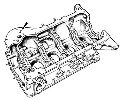
Figure 2-31. Cylinder size class marking on the block.
It is possible to bore cylinders for repair pistons, increased in diameter by 0.4 and 0.8 mm.
The main bearing caps are machined together with the cylinder block. Therefore, they are not interchangeable and have marks on the outer surface to differentiate them (see figure 2-19).
Technical condition check and repair
Check. Wash the cylinder block thoroughly and clean the oil channels. Blow and dry with compressed air, then inspect the cylinder block. Cracks in the bearings or other places of the cylinder block are not allowed.
If there is a suspicion of coolant getting into the crankcase, then check the cylinder block for leaks on a special stand. To do this, having plugged the openings of the cooling jacket of the cylinder block, pump water at room temperature into it under a pressure of 0.3 MPa (3 kgf/cm²). There should be no water leakage from the cylinder block within two minutes.
If oil is getting into the coolant, then without completely disassembling the engine, check for cracks in the cylinder block in the oil channel areas. To do this, drain the coolant from the cooling system, remove the cylinder head, fill the cooling jacket of the cylinder block with water and supply compressed air to the vertical oil channel of the cylinder block. If air bubbles appear in the water filling the cooling jacket, replace the cylinder block.
Check the plane of the cylinder block joint with the head using a ruler and a set of feeler gauges. The ruler is installed along the diagonals of the plane and in the middle in the longitudinal direction and across. The flatness tolerance should not be more than 0.1 mm.
Cylinder repair. Check if cylinder wear exceeds the maximum permissible value of 0.15 mm.
The cylinder diameter is measured with a bore gauge (figure 2-32) in four zones, both longitudinally and transversely to the engine (figure 2-33). A micrometer is used to set the bore gauge to zero.
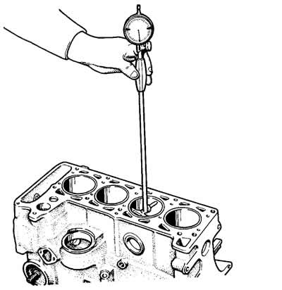
Figure 2-32. Measuring cylinders with a bore gauge:
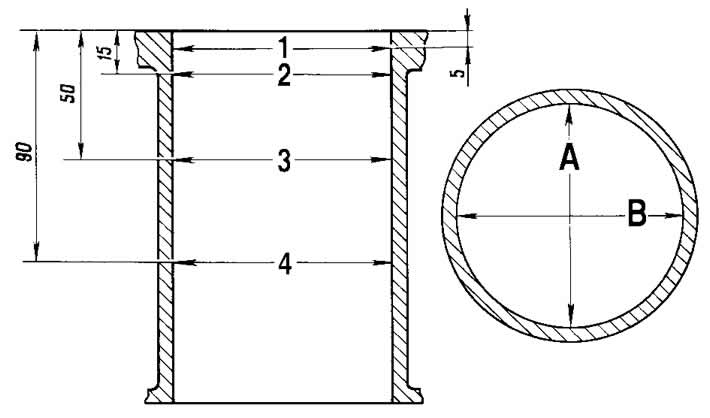
Figure 2-33. Cylinder measurement diagram:
A and B are the directions of measurements;
1, 2, 3 and 4 are the belt numbers.
In the zone of belt 1, the cylinders practically do not wear out. Therefore, the difference in measurements in the first and other belts can be used to judge the amount of wear of the cylinders.
If the maximum wear value is more than 0.15 mm, bore the cylinders to the nearest repair size, leaving an allowance of 0.03 mm on the diameter for honing. Then hone the cylinders, maintaining such a diameter that when installing the selected repair piston, the calculated gap between it and the cylinder is 0.025-0.045 mm.