


Features of the device
The camshaft is cast iron, rests on five journals and rotates in an aluminum bearing housing mounted on the cylinder head. The main dimensions of the camshaft and bearing housing are shown in Figure 2-56. The surfaces of the cams are bleached to increase wear resistance. The camshaft is held from axial movement by a thrust flange placed in the groove of the front bearing journal of the shaft.
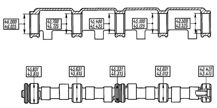
Figure 2-56. Main dimensions of the camshaft and bearing housing.
The camshaft is driven by the drive sprocket 8 (see figure 2-12) crankshaft by a single-row roller chain 1. The same chain also drives the sprocket 7 of the oil pump drive shaft. The chain drive has a hydraulic tensioner 4 with a shoe 2 and a chain damper 6.
The hydraulic tensioner provides chain tension immediately after installation.
Replacing the chain
To remove the chain, apply the parking brake and remove the battery.
Following the recommendations set out in the section "Removal and installation the engine", drain the coolant, remove the radiator assembly with fans, air filter, intake pipe hose.
Disconnect the ignition system wiring harness connectors from the phase sensor and from the crankshaft position sensor. Remove the phase sensor from the cylinder head.
Remove the cylinder head cover and turn the crankshaft until the mark on the camshaft sprocket aligns with the mark on the bearing housing (see figure 2-26), and the marks on the crankshaft damper with a long mark on the camshaft drive cover.
Loosen the tension of the accessory and compressor drive belts and remove the belts.
Loosen the camshaft sprocket mounting bolt.
Disconnect the oil supply pipe from the hydraulic tensioner, unscrew the two nuts and remove the hydraulic tensioner.
Remove the camshaft sprocket.
Engage fourth gear in the gearbox, unscrew the nut and remove the damper from the crankshaft.
Loosen the nuts securing the cover to the cylinder block and the bolts securing the oil pan to the cover, remove the camshaft drive cover with the gasket.
Loosen the chain tensioner shoe mounting bolt, chain guide mounting bolts, remove the shoe, guide and camshaft drive chain.
Install the chain in the reverse order of removal, following the recommendations set out in the subsection "Engine assembly". Lubricate the chain with engine oil before installation. Install new gaskets under the camshaft drive cover and cylinder head cover.
Checking the technical condition
Camshaft. No scoring, nicks, scratches, or aluminum drag from the bearing housings are allowed on the bearing journals of the camshaft. No wear of more than 0.5 mm, as well as scoring and faceted wear of the cams, are allowed on the working surfaces of the cams.
Install the camshaft with the outer journals on two prisms located on the surface plate and measure the radial runout of the middle journals with an indicator, which should be no more than 0.03 mm. If the runout exceeds the specified value, straighten the shaft on a straightening press.
Camshaft Bearing Housing: Wash and clean the bearing housing and oil supply channels.
Check the diameter of the holes in the bearings. If the gap between the camshaft journals and the bearings exceeds 0.2 mm (wear limit), replace the bearing housing.
The internal bearing surfaces must be smooth and free of burrs; if there is damage, replace the bearing housing. Check for cracks in the housing. If there are cracks, replace the camshaft bearing housing.
Hydraulic tensioner. When repairing, the tensioner body and plunger form a pair, in which replacement of one part by another after selection is not allowed, therefore the tensioner cannot be repaired and is replaced with a new one.
Check for excessive wear on the shoe and guide; replace them if necessary.
Camshaft drive chain. Wash the chain in kerosene, then check the condition of its links. No chips, cracks or other damage are allowed on the rollers and cheeks.
When the engine is running, the chain parts wear out, so the chain stretches. It is considered to be operational as long as the tensioner provides its tension, i.e. if the chain elongation does not exceed 4 mm.
Determine the chain length using device 67.7824-9521, the appearance of which is shown in Figure 2-57.
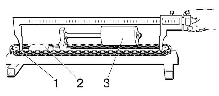
Figure 2-57. Chain wear (stretch) checker tool 67.7824-9521:
1 - roller;
2 - adjusting nut;
3 - counterweight.
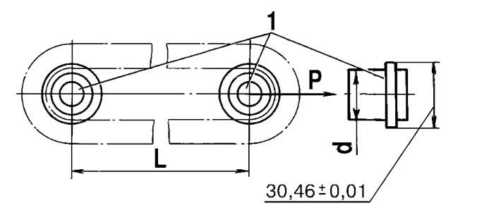
Figure 2-58. Chain wear (stretch) check diagram:
1- rollers.
The diagram for measuring the chain length is shown in Figure 2-58.
The 67.7824-9521 device has two stepped measuring rollers 1, on which the chain is installed when measuring its length. One of the rollers is fixed in the device body, and the second can move under the action of the measuring force P. With the help of the counterweight 3 (see figure 2-57) the chain is stretched with a force of 294 N (30 kgf) or 147 N (15 kgf). Adjusting nut 2 ensures that the counterweight axis is parallel to the base of the device.
The length of the chain is determined by the center distance L of the measuring rollers 1 (see figure 2-58). The new chain has a length L of 495.4-495.8 mm. If the chain is 499.8 mm long due to wear, it should be replaced.
Measure the chain length in the following sequence:
- stretch the chain with a force of 294 N (30 kgf), placing a counterweight of 3 (see figure 2-57) to the extreme right position, then reduce the force to 147 N (15 kgf) by moving the counterweight to the extreme left position;
- repeat both operations again;
- by measuring the internal distance between measuring rollers 1 with a caliper and adding to it the roller diameter d, you get the length of the chain L (distance between the axes of the measuring rollers).
Before installing on the engine, lubricate the chain with engine oil.
[The article is based on data from the website CHEVYMAN.RU]