


Contents: Features of the device ↧ Selecting a piston for a cylinder ↧ Disassembly and assembly ↧ Checking the technical condition ↧
Features of the device
The main dimensions of the connecting rod and piston group are shown in Figure 2-34.
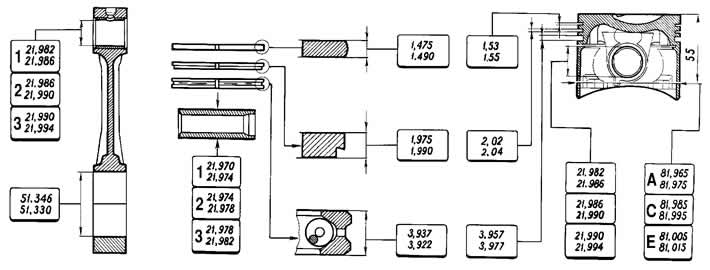
Figure 2-34. Main dimensions of the connecting rod and piston group
The piston is cast aluminum. The piston weight is strictly maintained during manufacturing. Therefore, when assembling the engine, it is not necessary to select pistons of the same group by weight.
According to the outer diameter, pistons are divided into five classes (A, B, C, D, E) through 0.01 mm. The outer surface of the piston has a complex shape. It is barrel-shaped in height and oval in cross-section. Therefore, it is necessary to measure the piston diameter only in the plane perpendicular to the piston pin, at a distance of 55 mm from the piston bottom.
According to the diameter of the hole for the piston pin, pistons are divided into three classes (1, 2, 3) through 0.004 mm. The classes of piston diameters and holes for the piston pin are stamped on the piston bottom (figure 2-35).
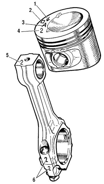
Figure 2-35. Piston and connecting rod markings:
1 - arrow for orienting the piston in the cylinder;
2 - repair size;
3 - piston class;
4 - piston pin bore class;
5 - connecting rod class by piston pin bore;
6 - cylinder number.
Pistons of repair sizes are manufactured with an outer diameter increased by 0.4 and 0.8 mm. The bottoms of these pistons are marked with a triangle or square. The triangle corresponds to an increase in the outer diameter by 0.4 mm, and the square - by 0.8 mm.
The arrow on the piston bottom shows how to correctly orient the piston when installing it in the cylinder. It should be directed towards the camshaft drive.
The piston pin is steel, hollow, floating type, i.e. it rotates freely in the piston bosses and connecting rod bushing. The pin is fixed in the piston by two steel retaining rings.
According to the outer diameter, the pins are divided into three classes, each in 0.004 mm. The class is marked with paint on the end of the pin: blue mark - first, green - second, and red - third class.
Piston rings — made of cast iron. Upper compression ring — with chrome-plated barrel-shaped outer surface. Lower compression ring of scraper type. Oil scraper ring — with chrome-plated working edges and with expansion coil spring (expander).
On rings of repair sizes, the digital marking "40" or "80" is placed, which corresponds to an increase in the outer diameter by 0.4 or 0.8 mm.
Connecting rod — steel, forged. The connecting rod is processed together with the cover and therefore they are not interchangeable separately. To avoid mixing up the covers and connecting rods during assembly, they are stamped with number 6 (see figure 2-35) cylinder in which they are installed. When assembling, the numbers on the connecting rod and cover should be on the same side
A steel-bronze bushing is pressed into the upper head of the connecting rod. According to the diameter of the hole in this bushing, the connecting rods are divided into three classes, each with a 0.004 mm increment (the same as pistons). Class 5 number is stamped on the upper head of the connecting rod.
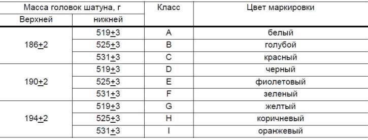
By the weight of the upper and lower heads, connecting rods are divided into classes (Table 2-1), marked with paint on the connecting rod rod. Connecting rods of the same weight class must be installed on the engine. The weight of the connecting rods can be adjusted by removing metal from the bosses on the heads to the minimum dimensions of 16.5 and 35.5 mm (figure 2-36).
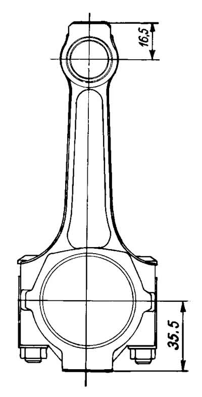
Figure 2-36. Places where metal may be removed when adjusting the weight of the upper and lower connecting rod heads.
Table 2-1. Connecting rod classes by weight of upper and lower heads
Selecting a piston for a cylinder
Calculated minimum clearance between piston and cylinder (for new parts) is 0.025-0.045 mm. It is defined as the difference between the minimum cylinder size and the maximum piston size and is achieved by installing pistons of the same class as the cylinders. The maximum permissible clearance (when parts wear out) — 0.15 mm.
If the clearance of a previously used engine exceeds 0.15 mm, then it is necessary to re-select the pistons to the cylinders so that the clearance is as close as possible to the calculated one.
Spare parts are supplied with pistons of classes A, C, E. These classes are sufficient to select a piston for any cylinder during engine repair, since pistons and cylinders are divided into classes with a small overlap of sizes. For example, a piston of class C can fit cylinders of classes B and D.
Disassembly and assembly
Disassembly. Remove the piston pin retaining rings from the piston, remove the pin and disconnect the connecting rod from the piston. Remove the piston rings.
Connecting rod bolts are pressed into the connecting rod. Therefore, in order not to disturb the bolt fit in the connecting rod, it is not allowed to press out the bolts from the connecting rods when disassembling the engine and connecting rod-piston group.
If some parts of the connecting rod and piston group are not damaged and slightly worn, they can be used again. Therefore, when disassembling, mark them so that later you can assemble the group with the same parts and install it in the previous engine cylinder.
Assembly. Before assembly, match the pin to the piston and connecting rod. For new parts, the class of the holes for the pin in the connecting rod and piston must be identical to the class of the pin. For used parts, for correct mating, it is necessary that the piston pin, lubricated with engine oil, should enter the piston hole from the pressure of the thumb (figure 237) and smoothly exit under its own weight from the piston boss holes, being in a vertical position, as shown in Figure 2-38. If additional force is required to exit the piston pin from the piston boss holes, replace the piston pin with a lower grade.
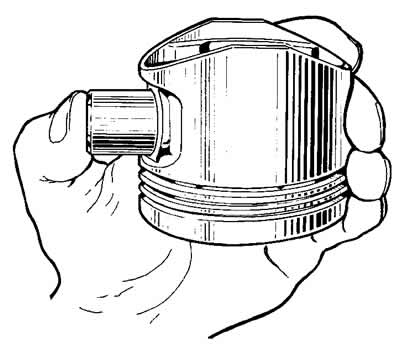
Figure 2-37. Installing the piston pin.
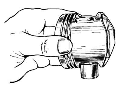
Figure 2-38. Checking the piston pin fit.
If a first category pin was inserted into the piston, replace the piston pin and connecting rod. The connecting rod and piston group is assembled in the reverse order of disassembly. After installing the piston pin, lubricate it with engine oil through the holes in the piston bosses.
Install piston rings in the following order:
- lubricate the piston grooves and piston rings with engine oil. Orient the piston rings so that the upper compression ring lock is at an angle of 45° to the axis of the piston pin, the lower compression ring lock is at an angle of approximately 180° to the axis of the upper compression ring lock, and the oil scraper ring lock is at an angle of approximately 90° to the axis of the upper compression ring lock
- install the lower compression ring with the notch facing down (see figure 2-36). If the ring is marked "Top" or "TOP", then install the ring with the mark facing up (to the piston bottom).
Before installing the oil scraper ring, check that the joint of the spring expander is located on the side opposite the ring lock.
Checking the technical condition
Clean the piston from carbon deposits and remove all deposits from the piston and connecting rod oil passages.
Carefully inspect the parts. Cracks of any kind on the piston, piston rings, pin, connecting rod and its cover are not allowed. If there are deep scratches on the working surface of the liners, replace the liners with new ones.
Check the clearance between the piston rings and the grooves with a set of feeler gauges, as shown in Figure 2-39, by inserting the ring into the corresponding groove. Calculated clearance (rounded to 0.01 mm) for new parts is 0.04-0.07 mm for the upper compression ring, 0.03-0.06 mm for the lower one, and 0.02-0.05 mm for the oil scraper ring. The maximum permissible clearances during wear are 0.15 mm.
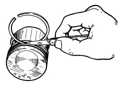
Figure 2-39. Checking the clearance between the piston rings and grooves.
Check the gap in the piston ring lock with a set of feeler gauges by inserting the rings into the cylinder (figure 2-40), having a bore diameter equal to the nominal diameter of the ring with a tolerance of ±0.003 mm.
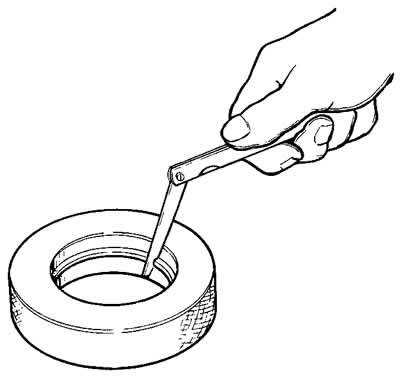
Figure 2-40. Checking the gap in the ring lock.
The gap should be within 0.25-0.45 mm for all new rings. The maximum allowable gap when worn is 1 mm.
[The article is reprinted from the website: «CHEVYMAN.RU»]