
Disconnect from throttle body 5 (see figure 2-6) hoses 4 for supplying and draining coolant, as well as tube 2 for crankcase ventilation at idle speed. Remove the throttle pipe with the gasket by unscrewing the nuts securing it to the receiver 6.
Remove hose 1 (figure 2-8) fuel line, disconnecting it from the fuel rail 2. Unscrew the five nuts, remove the receiver 6 (see figure 2-6) with gasket and engine screen bracket.
Disconnect the wiring harness from the injectors, remove the fuel rail 2 (figure 2-8), unscrewing two bolts 3 securing to the intake pipe.
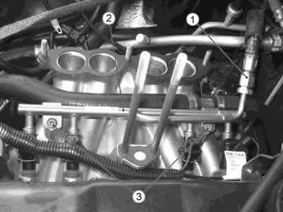
Figure 2-8. Removing the power supply system components:
1 - fuel line hose;
2 - fuel rail;
3 - bolt.
Remove the starter shield.
Loosen the nuts and remove the intake pipe.
Unscrew nuts 7 (figure 2-9) and remove screen 6. Unscrew nuts 1, 4 and remove exhaust manifold 2.
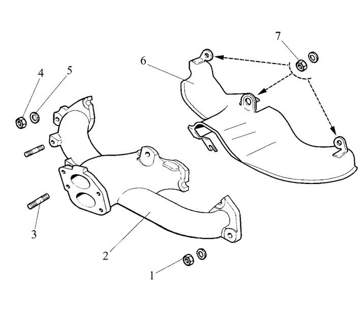
Figure 2-9. Removing the exhaust manifold:
1 - nut;
2 - exhaust manifold;
3 - hairpin;
4 - nut;
5 - washer;
6 - collector screen;
7 - screen mounting nut.
Remove the ignition coil from the left side of the engine, and the knock sensor from the right. Remove the air conditioning compressor following the recommendations in the subsection "Air conditioning system".
Loosen nuts 8 (see figure 2-63) unscrew bolt 5 and remove auxiliary drive belt 7. Remove the generator, generator bracket, tensioner.
Remove the coolant pump.
Unscrew bolts 2 (see figure 2-10) and remove the power steering pump 9.
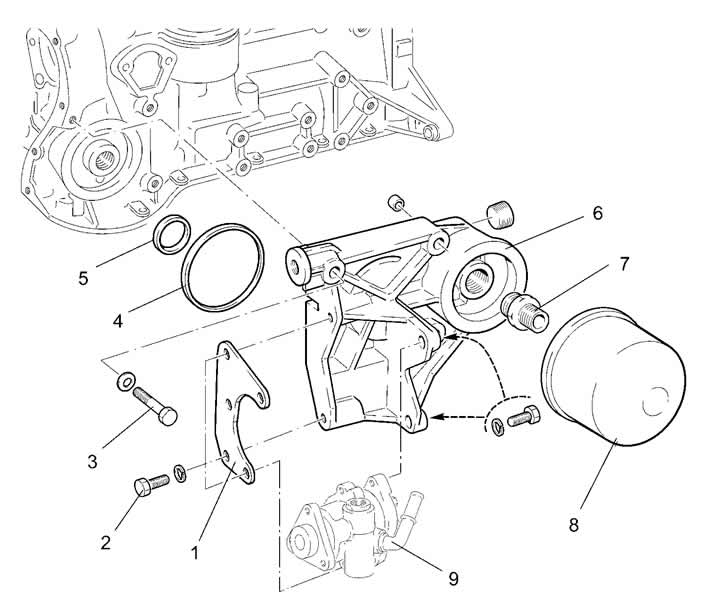
Figure 2-10. Removing the oil filter:
1 - plate;
2 - power steering pump mounting bolt;
3 - oil filter bracket mounting bolt;
4 - sealing ring;
5 - gasket;
6 - oil filter bracket;
7 - nipple;
8 - oil filter;
9 - power steering pump.
Using the tool, unscrew and remove the oil filter 8 with the gasket. Unscrew the bolts 3 and remove the oil filter bracket 6.
Remove the coolant outlet pipe and the coolant drain pipe to the heater from the cylinder head.
Remove the crankshaft damper, securing the flywheel with the A.60330/R locking tool (figure 2-11) and unscrewing the nut with a key.
Unscrew sensor 11 (Fig. 2-12) of the oil pressure control lamp. Remove the crankcase ventilation breather cover, crankcase, oil pump drive gear retainer, oil pump. Remove the oil separator drain pipe retainer and remove the crankcase ventilation oil separator.
Remove the cylinder head cover, with the engine screen and accelerator cable brackets. Remove the camshaft drive cover. Unscrew the bolts securing the camshaft sprockets and the oil pump drive shaft.
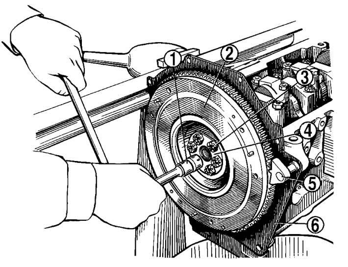
Figure 2-11. Removing the flywheel:
1 - key;
2 - flywheel;
3 - flywheel mounting bolt;
4 - washer;
5 - A.60330/R retainer for holding the flywheel from turning;
6 - front cover of the clutch housing.
The engine is equipped with hydraulic tensioners and oil supply pipes of two types. The pipes and hydraulic tensioners are not interchangeable.
For the first option: unscrew the nipple of tube 4 (figure 2-12) oil supply and disconnect it from tensioner 6. Unscrew the nuts securing the tensioner to the cylinder head, remove it and, having unscrewed the bolt, remove shoe 2 of chain tensioner 1.
Unscrew the nipple of the oil supply pipe 4 from the adapter 9, remove the pipe.
Unscrew bolt 10, remove adapter 9 and sealing washers.
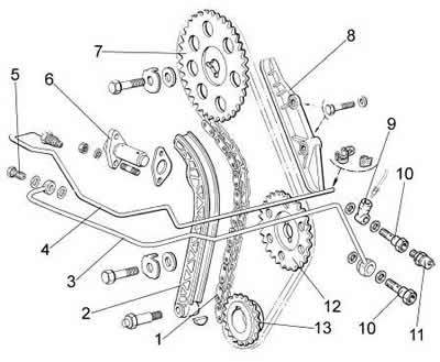
Figure 2-12. Elements of the chain tensioning mechanism:
1 - chain;
2 - tensioner shoe;
3 - oil supply pipe to the tensioner (option 2);
4 - oil supply pipe to the tensioner (option 1);
5 - tube mounting bolt;
6 - chain tensioner;
7 - camshaft sprocket;
8 - pacifier;
9 - adapter;
10 - tube mounting bolt;
11 - Oil pressure warning light sensor;
12 - oil pump drive shaft sprocket;
13 - crankshaft sprocket.
For the second option (installed since 08.2008.): unscrew bolt 5 securing tube 3 for supplying oil to tensioner 6, remove sealing washers.
Unscrew bolt 10 securing tube 3 to the cylinder block, remove the tube and sealing washers.
Remove sprockets 7 and 5 of the oil pump drive, camshaft and chain.
Loosen the stud nuts 4 (figure 2-13). Remove the camshaft bearing housing. After unscrewing the stud nuts 4 and removing the thrust flange 1, carefully, so as not to damage the bearing housing support surface, remove the camshaft.
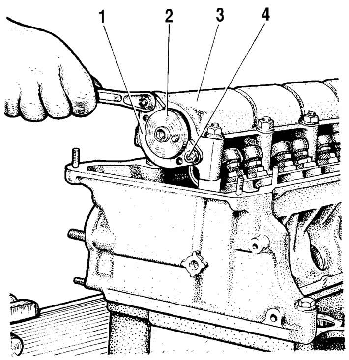
Figure 2-13. Removing the camshaft thrust flange:
1 - thrust flange;
2 - camshaft;
3 - bearing housing;
4 - thrust flange mounting stud.
Loosen the cylinder head mounting bolts and remove it.
Remove the thrust flange 1 (figure 2-14) oil pump drive shaft and remove the shaft from the cylinder block.
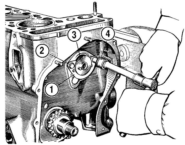
Figure 2-14. Removing the oil pump drive shaft:
1 - thrust flange;
2 - flange mounting bolt;
3 - oil pump drive shaft;
4 - key.
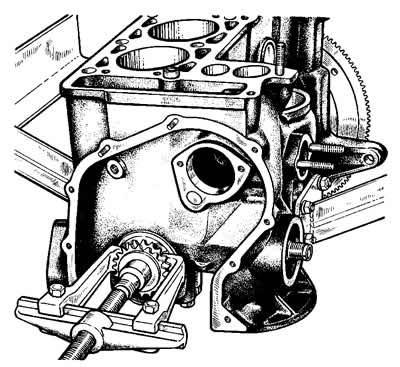
Figure 2-15. Removing the crankshaft sprocket with a universal puller.
Use a universal puller to remove the sprocket from the crankshaft (figure 2-15).
Loosen the connecting rod bolt nuts, remove the connecting rod caps and carefully remove the pistons with connecting rods through the cylinders. Mark the piston, connecting rod, main and connecting rod bearing shells so that they can be installed in their original place during assembly.
Warning: When removing the connecting rod and piston group, it is not allowed to press out the connecting rod bolts from the connecting rods.
Install lock 5 (see figure 2-11), unscrew bolts 3, remove washer 4 and flywheel from the crankshaft. Remove the front clutch housing cover.
Using a special puller, remove the gearbox input shaft bearing from its seat in the crankshaft (figure 2-16).
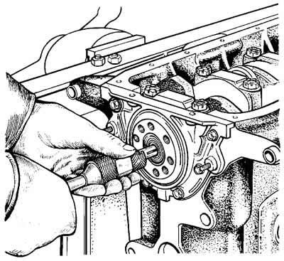
Figure 2-16. Pressing out the gearbox shaft bearing from the crankshaft.
Remove the crankshaft oil seal retainer.
Unscrew the main bearing cap bolts, remove them together with the lower bearing shells, remove the crankshaft, upper bearing shells and thrust half rings on the rear support.
Information taken from the official website: ChevyMan.ru