


Note: Part removal procedures not covered here are described above in the relevant sections "Car repair". Ignore the preliminary operations that were performed when removing the engine.
1. Remove the drive belts of the auxiliary units and the air conditioning compressor.
2. Remove the crankshaft pulley.
3. Remove the torque converter drive clutch.
4. Remove the oil dipstick tube.
5. Remove the exhaust manifolds.
6. Remove the coolant pump, see chapter "Cooling system".
7. Remove the intake manifold.
Note: The intake manifold, throttle body, fuel rail and injectors can be removed as a single unit. Do not disassemble the intake manifold unless repair of these parts is required.
8. Remove the throttle body, see section "Intake manifold".
9. Remove the fuel manifold and injectors, see section "Intake manifold".
10. Remove the air bleed tube from the cooling system, see chapter "Cooling system".
11. Remove the block camber cover or oil manifold. If necessary, remove the oil pressure sensor and oil filter from the camber cover or oil manifold.
12. Remove the valve covers.
13. Remove the rocker arms and push rods.
14. Remove the head of the left half block.
15. Remove the head of the right half block.
16. Remove the pushrod guides together with the pushrods.
17. Remove the oil filter. If necessary, remove the oil filter adapter.
18. Remove the oil pan.
19. Remove the front engine cover.
20. Remove the rear engine cover.
21. Remove the oil receiver and crankshaft deflector.
22. Remove the oil pump.
23. Remove the chain and sprocket (variable valve timing system clutch) camshaft. Remove the chain tensioner.
24. Remove the crankshaft sprocket.
25. Remove the camshaft.
26. Remove the pistons, connecting rods and connecting rod bearings:
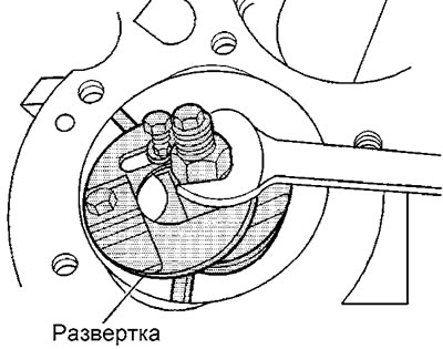
a) If necessary, use a reamer to remove the wear ridge where the upper compression ring stops at TDC.
b) Apply cylinder number marks to the connecting rod body and cap.
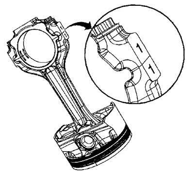
Caution: Connecting rod caps are not interchangeable, after removing the piston and connecting rod, immediately install the cap on the connecting rod.
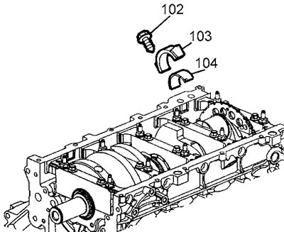
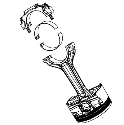
c) Unscrew the bolts (102) securing the connecting rod cover, remove the cover (103) and the upper connecting rod bearing shell (104).
d) Screw soft metal guides into the connecting rod to protect the surfaces of the connecting rod journal and the cylinder walls.
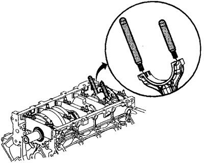
d) Using light blows from a plastic hammer, knock the connecting rod and piston out of the cylinder block.
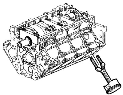
e) Install the bearing cap into the connecting rod and liners.
Install the cover according to the previously made marks and tighten the cover mounting bolts by hand.
27. Remove the crankshaft:
Caution: Before removing the crankshaft main bearing caps, mark them with the installation location numbers; the main bearing caps are not interchangeable.
Caution: Do not reinstall the M8 main cover tie bolt.
a) Loosen the bolt (702) securing the crankshaft position sensor.
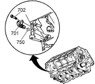
b) Remove the crankshaft position sensor (701).
c) If necessary, remove the sealing ring (750) from the sensor.
d) Unscrew the tie bolts (127).
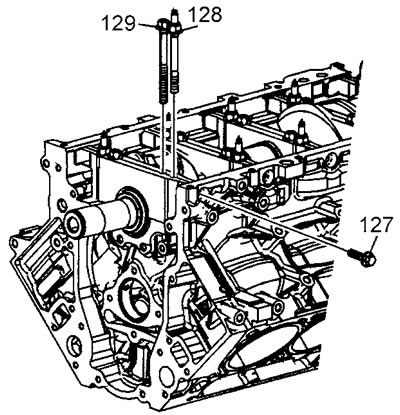
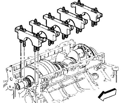
d) Unscrew the bolts (129) and stud bolts (128) securing the main bearing caps.
e) Place an inertia hammer on the cover and tighten the adapter mounting bolts (2). Tightening torque 11 Nm.
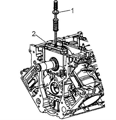
g) Remove the main bearing caps.
c) Remove the crankshaft.
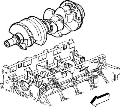
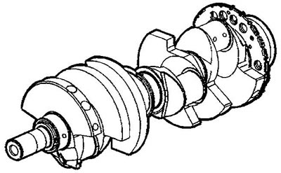
Caution: When servicing the crankshaft, be careful not to damage the teeth of the crankshaft position sensor timing ring. Notches, burrs, and other defects in the teeth may affect the operation of the OBD II on-board diagnostic system.
i) Place the crankshaft on the workbench on two wooden blocks.
k) Remove the main bearing shells from the block and caps. Place the shells so that they fit into their old positions during assembly.
28 Remove the cylinder block plugs: Note: If the plug seals are not damaged, they can be reinstalled.
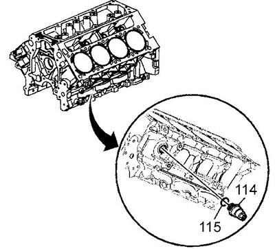
a) Remove the coolant heater (114) and seal (115).
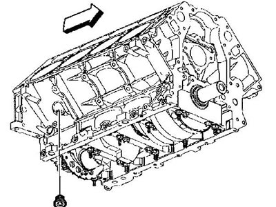
b) Remove the plug and seal of the rear drain hole of the right half-block.
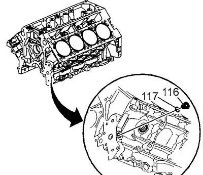
c) Remove the front plug (116) and seal (117) of the oil line of the left half-block.
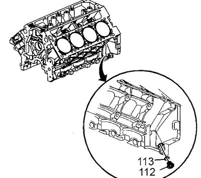
d) Remove the rear plug (112) and seal (113) of the oil line of the left half-block.
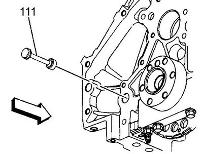
d) Remove the rear plug (111) and the oil line seal of the right half block.
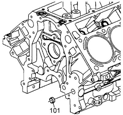
e) Remove the front plug (101) of the right half-block oil line. Remove this plug only if necessary. A NEW plug must be installed.
g) Unscrew the bolt (739) securing the knock sensor (718) of the left half-block, remove the sensor.
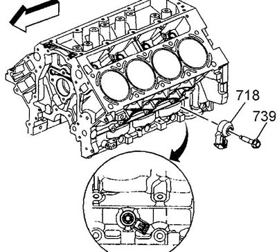
i) Unscrew the bolt (739) securing the knock sensor (718) of the right half-block, remove the sensor.

The original text can be found on the website CHEVYMAN.RU