


Plastic gauge method
Attention:
- The crankshaft main and connecting rod bearing shells are high-precision products. The main bearing caps are machined together with the block to provide the required bearing clearance and should not be filed to ensure the bearing installation tension.
- Do not rotate the crankshaft with the plastic gauge installed in the bearing.
- Main bearing clearance is a critical value. Excessive clearance can affect the crankshaft position sensor signals and cause OBD II diagnostic system failures.
- Before removing the main bearing cap, remove the cap tie bolts.
1. Loosen the bolts securing the main or connecting rod bearing cap, remove the cap and the liner.
2. Place a plastic gauge on the crankshaft journal. The length of the gauge should be equal to the width of the crankshaft journal.
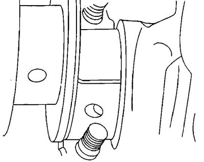
3. Install the bearing cover together with the liner, tighten the mounting bolts to the specified torque.
4. Remove the bearing cap and liner.
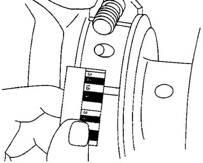
5. Using the scale printed on the envelope with the gauges, determine the clearance in the bearing along the width of the gauge at its widest point.
- If the gauge width irregularity shows a main bearing clearance variation greater than 0.025 mm, measure the journal.
- If the main bearing clearance cannot be brought within specification, replace the crankshaft or cylinder block.
Direct measurement method
1. Measure the outside diameter of the crankshaft journal in two places along the journal length and in two mutually perpendicular planes. To determine the clearance, take the largest diameter value.
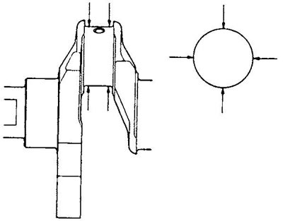
2. Install both bearing shells, tighten the cover mounting bolts to the specified torque.
3. Measure the inner diameter of the bearing in two places along the length of the liner and in two mutually perpendicular planes. To determine the clearance, take the smallest diameter value.
4. Calculate the bearing clearance.
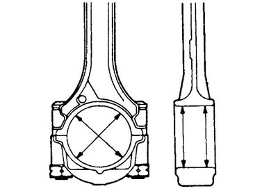
Checking the clearance in the crank pin |
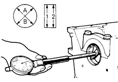
Checking the clearance in the main journal |
The original material is located on the website: ChevyMan