


Car suspension repair Chevrolet Tahoe 2 and 3

Wheel installation data
Table: Wheel alignment data. Models before 2007 (GMT800) Table. Wheel alignment data. Models since 2007 (GMT900) Note: The kingpin caster is measured relative...
Table: Wheel alignment data. Models before 2007 (GMT800) Table. Wheel alignment data. Models since 2007 (GMT900) Note: The kingpin caster is measured relative...

Wheel angle adjustment
Poor directional stability and vibration are not always the result of improper wheel alignment. One possible cause is an imbalance in the wheel or wheels....
Poor directional stability and vibration are not always the result of improper wheel alignment. One possible cause is an imbalance in the wheel or wheels....

General description of the front suspension
Depending on the configuration, models may be equipped with a rack-type suspension (spring) or torsion suspension. Accordingly, there are differences in...
Depending on the configuration, models may be equipped with a rack-type suspension (spring) or torsion suspension. Accordingly, there are differences in...

Lower control arm of the front suspension
Removal 1. Raise the vehicle and place safety posts under the frame. 2. Place a safety stand under the lower suspension arm. 3. Remove the front wheel. 4....
Removal 1. Raise the vehicle and place safety posts under the frame. 2. Place a safety stand under the lower suspension arm. 3. Remove the front wheel. 4....

Upper control arm front suspension
Removal 1. Raise the vehicle and place safety stands under the frame. 2. Remove the front wheel. 3. If the electronically controlled suspension is installed,...
Removal 1. Raise the vehicle and place safety stands under the frame. 2. Remove the front wheel. 3. If the electronically controlled suspension is installed,...

Front suspension knuckle
Removal 1. Raise the vehicle and place safety stands under the frame. 2. Remove the front wheel. 3. Place a safety stand under the lower suspension arm. 4....
Removal 1. Raise the vehicle and place safety stands under the frame. 2. Remove the front wheel. 3. Place a safety stand under the lower suspension arm. 4....

Front suspension wheel hub
Removal 1. Raise the vehicle and place safety posts under the frame. 2. Remove the front wheel. 3. Remove the brake disc. 4. Remove the brake hose and wheel...
Removal 1. Raise the vehicle and place safety posts under the frame. 2. Remove the front wheel. 3. Remove the brake disc. 4. Remove the brake hose and wheel...

Front suspension torsion bar
Removal Caution: When servicing the torsion bar, do not damage the protective coating of the torsion bar. Damage to the coating will lead to premature failure...
Removal Caution: When servicing the torsion bar, do not damage the protective coating of the torsion bar. Damage to the coating will lead to premature failure...

Front suspension shock absorber
Removal Note: Front suspension shock absorbers are multifunctional. In addition to damping suspension vibrations, they also provide a limitation of the full...
Removal Note: Front suspension shock absorbers are multifunctional. In addition to damping suspension vibrations, they also provide a limitation of the full...
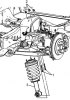
Front suspension strut
Removal 1. Raise the vehicle and place safety stands under the frame. 2. Remove the front wheels. 3. Disconnect the steering from the steering knuckle. 4. To...
Removal 1. Raise the vehicle and place safety stands under the frame. 2. Remove the front wheels. 3. Disconnect the steering from the steering knuckle. 4. To...

Front suspension travel limiter
Removal and installation Note: Installation is carried out in reverse order. 1. Raise the vehicle and place safety posts under the frame. 2. 1500 Series:...
Removal and installation Note: Installation is carried out in reverse order. 1. Raise the vehicle and place safety posts under the frame. 2. 1500 Series:...

Front suspension anti-roll bar
Removal 1. Raise the vehicle and place safety stands under the frame. 2. Remove the front wheels. 3. Remove the stabilizer links. 4. Unscrew the nut (1)...
Removal 1. Raise the vehicle and place safety stands under the frame. 2. Remove the front wheels. 3. Remove the stabilizer links. 4. Unscrew the nut (1)...
Front suspension ball joints
1. Remove the suspension arm (see the relevant section). 2. Place the suspension arm in a vice. 3. Drill out the rivets securing the ball joint to the lever....
1. Remove the suspension arm (see the relevant section). 2. Place the suspension arm in a vice. 3. Drill out the rivets securing the ball joint to the lever....

Lower trailing arm rear suspension
Removal 1. Raise the vehicle and place safety stands under the frame. 2. Place a temporary support under the bridge beam. 3. Unscrew the nuts and bolts...
Removal 1. Raise the vehicle and place safety stands under the frame. 2. Place a temporary support under the bridge beam. 3. Unscrew the nuts and bolts...

Upper trailing arm rear suspension
Removal 1. Raise the vehicle and place safety stands under the frame. 2. Place a temporary support under the bridge beam. 3. If the suspension is...
Removal 1. Raise the vehicle and place safety stands under the frame. 2. Place a temporary support under the bridge beam. 3. If the suspension is...

Panhard rod rear suspension
Removal 1. Raise the vehicle and place safety stands under the frame. 2. Place a temporary support under the bridge beam. 3. Disconnect the parking brake cable...
Removal 1. Raise the vehicle and place safety stands under the frame. 2. Place a temporary support under the bridge beam. 3. Disconnect the parking brake cable...

Rear Suspension Spring (1500 Models)
Removal 1. Raise the vehicle and place safety stands under the frame. 2. Place a temporary support (jack) under the bridge beam. 3. If the suspension is...
Removal 1. Raise the vehicle and place safety stands under the frame. 2. Place a temporary support (jack) under the bridge beam. 3. If the suspension is...

Rear Suspension Leaf Spring (2500 Models)
Removal 1. Raise the vehicle and place safety stands under the frame. 2. Place a temporary support (jack) under the bridge beam. 3. If the suspension is...
Removal 1. Raise the vehicle and place safety stands under the frame. 2. Place a temporary support (jack) under the bridge beam. 3. If the suspension is...

Rear suspension shock absorber
Removal 1. Raise the vehicle and place safety stands under the frame. 2. If the suspension is electronically controlled, disconnect the shock absorber wiring...
Removal 1. Raise the vehicle and place safety stands under the frame. 2. If the suspension is electronically controlled, disconnect the shock absorber wiring...

Rear suspension travel limiter
Removal 1. Raise the vehicle and place safety stands under the frame. 2. Loosen the limiter mounting bolt. Tightening torque 32 Nm. Series 1500 (GMT800/900),...
Removal 1. Raise the vehicle and place safety stands under the frame. 2. Loosen the limiter mounting bolt. Tightening torque 32 Nm. Series 1500 (GMT800/900),...

Rear suspension stabilizer bar
Removing and installing the anti-roll bar Removal 1. Raise the vehicle and place safety stands under the frame. 2. Unscrew the stabilizer link ball joint nut....
Removing and installing the anti-roll bar Removal 1. Raise the vehicle and place safety stands under the frame. 2. Unscrew the stabilizer link ball joint nut....

Automatic body leveling (ALC) and shock absorber stiffness control (ESC)
GMT800. Suspension details: (2500 series, right rear). 1 - bridge beam, 2 - body height sensor, 3 - sensor lever, 4 - body height sensor connector. GMT800....
GMT800. Suspension details: (2500 series, right rear). 1 - bridge beam, 2 - body height sensor, 3 - sensor lever, 4 - body height sensor connector. GMT800....

ALC and ESC control unit
GMT800, Escalade EXT 1. Lift the rear seat cushion to access the suspension control module. 2. Remove the holders (1) of the control unit cover (2). 3. Remove...
GMT800, Escalade EXT 1. Lift the rear seat cushion to access the suspension control module. 2. Remove the holders (1) of the control unit cover (2). 3. Remove...

Body height sensor rod
Removal Warning: Do not attempt to remove the tie rod from the ball joint. If the tie rod needs to be replaced or disconnected, the following steps must be...
Removal Warning: Do not attempt to remove the tie rod from the ball joint. If the tie rod needs to be replaced or disconnected, the following steps must be...

Body height sensor
GMT800. Front sensor 1. Raise the vehicle and place safety stands under the frame. 2. Disconnect the sensor wire connector from the vehicle wire harness...
GMT800. Front sensor 1. Raise the vehicle and place safety stands under the frame. 2. Disconnect the sensor wire connector from the vehicle wire harness...

Ride Height Control Compressor
Removal 1. Raise the vehicle and place safety stands under the frame. 2. Disconnect the tube (1) from the air dryer. Caution: Before disconnecting the air...
Removal 1. Raise the vehicle and place safety stands under the frame. 2. Disconnect the tube (1) from the air dryer. Caution: Before disconnecting the air...

Air tube between rear shock absorbers and compressor
Repair Caution: An air leak in the air tube between the rear shock absorbers and the compressor will result in increased compressor run time. After...
Repair Caution: An air leak in the air tube between the rear shock absorbers and the compressor will result in increased compressor run time. After...

Dehumidifier and air pressure sensor
Removal 1. Remove the ride height control compressor. 2. Disconnect the air pressure sensor wiring connector. 3. Loosen the screw securing the dehumidifier/air...
Removal 1. Remove the ride height control compressor. 2. Disconnect the air pressure sensor wiring connector. 3. Loosen the screw securing the dehumidifier/air...
Tire pressure system
The Tire Pressure System (TPM) alerts the driver when a significant loss of air pressure is detected in any of the four tires. The system uses a passenger door...
The Tire Pressure System (TPM) alerts the driver when a significant loss of air pressure is detected in any of the four tires. The system uses a passenger door...

Tire pressure sensor
Removal 1. Raise the vehicle and place safety posts under the frame. 2. Remove the wheel. 3. Remove the tire from the wheel. Attention: before removing the...
Removal 1. Raise the vehicle and place safety posts under the frame. 2. Remove the wheel. 3. Remove the tire from the wheel. Attention: before removing the...
This section is available at russian, bulgarian, belarusian, ukrainian, serbian, croatian, romanian, polish, slovak, hungarian
See similar sections on Chevrolet cars:
Chassis: Wheel suspension Chevrolet Aveo T250 (2006-2011)
Chassis: Car suspension Chevrolet Captiva 1 (2006-2018)
Chassis: Suspension and shock absorbers Chevrolet Niva 1 (2002-2016)
Chassis: Car suspension Chevrolet Lumina 1 (1989-1994)
Chassis: Wheel suspension Chevrolet Aveo T250 (2006-2011)
Chassis: Car suspension Chevrolet Captiva 1 (2006-2018)
Chassis: Suspension and shock absorbers Chevrolet Niva 1 (2002-2016)
Chassis: Car suspension Chevrolet Lumina 1 (1989-1994)
Share information:
- General information
- Vehicle characteristics
- Vehicle device
- Manual
- Maintenance
- Power unit
- Engine repair
- Engine overhaul
- Cooling system
- Injection and control system
- Exhaust system
- Engine electrical equipment
- Transmission
- Automatic gearbox 4L60, 4L65, 4L70
- Automatic gearbox 6L50, 6L80, 6L90
- Transfer case
- Drive shafts and cardan
- Front drive axle
- Rear drive axle
- Chassis
- Car suspension
- Steering
- Brake system
- Body (until 2007)
- Exterior (external elements)
- Interior (internal elements)
- Doors, locks and windows
- Heating and air conditioning
- Security System (SRS)
- Body (since 2007)
- Exterior (external elements)
- Doors, locks and windows
- Interior (internal elements)
- Electrical equipment
- Electrical appliances (until 2007)
- Lighting and lamps (until 2007)
- Audio system (until 2007)
- Electrical appliances (since 2007)
- Lighting and lamps (since 2007)
- Audio system (since 2007)
- Wiring diagrams (2000-2005)
- Wiring diagrams (2005-2007)
- Wiring diagrams (since 2007)
- General information
- User manual
- Maintenance
- Power unit
- Engine in a car
- Engine removed
- Cooling system
- Heating and air conditioning
- Fuel and exhaust systems
- Decreased toxicity
- Transmission
- Manual gearbox
- Automatic gearbox
- Transfer case
- Clutch and drive shafts
- Chassis
- Brake system
- Car suspension
- Steering
- Body
- Repair of body elements
- Electrical equipment
- Engine electrics
- Equipment and devices
- Electrical circuits