
Necessary equipment
KM-470-B Angular Torque Indicator
Inspection Procedure - Crankshaft
1. Lubricate the main bearings with engine oil.
2. Install the upper main bearings into the crankshaft journals of the cylinder block.
3. Install the lower main bearings into the main bearing caps.
4. Install the crankshaft.
5. Check the crankshaft axial clearance with the main bearings installed.
6. Check the permissible axial clearance of the crankshaft. Follow the point "Engine Specifications" in this section.
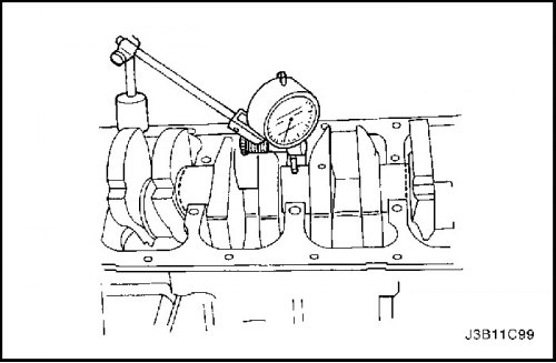
7. When the crankshaft is installed in the front and rear main bearings, check the crankshaft center journal for permissible eccentricity (runout). Follow step "Engine Specifications" in this section.

Important: Lubricate the crankshaft journals with grease and lightly lubricate the main bearings to prevent the plastic gauging wire from coming off when removing the main bearing caps.
8. Check all main bearing clearances using a commercially available plastic gauging wire (elastic calibration wire).
9. Cut a plastic gauging wire to the same size as the bearing width. Place it axially between the crankshaft journals and the main bearings.
10. Install the main bearing caps.
11. Install the main bearing cap screws.
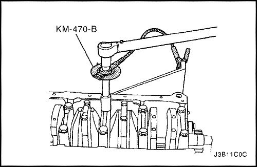
Tighten
Tighten the main bearing cap bolts to 50 N·m (37 lb-ft). Using the KM-470-B angular torque gauge, tighten the main bearing cap bolts an additional 45° plus 15°.

12. Remove the main bearing caps.
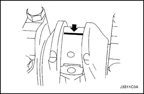
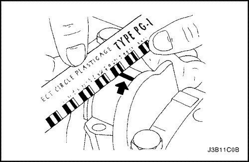
13. Measure the width of the flattened plastic gauging wire using a ruler. (Plastic calibration wire is available for different tolerances).
14. Check the bearing clearances for permitted tolerances. Follow step "Engine Specifications" in this section.
Inspection procedure - connecting rods
1. Lubricate the connecting rod bearings with engine oil.
2. Install the upper connecting rod bearings into the connecting rod journals.
3. Install the lower connecting rod bearings into the connecting rod bearing caps.
Important: Lubricate the connecting rod bearing journals and lightly lubricate the connecting rod bearings to prevent the plastic gauging wire from coming off when removing the connecting rod bearing caps.
4. Check all connecting rod bearing clearances using a commercially available plastic gauging wire (elastic calibration wire).
5. Cut a plastic gauging wire to the same size as the bearing width. Place it axially between the connecting rod journals and the connecting rod bearings.
6. Install the connecting rod bearing caps.
7. Install the connecting rod bearing cap screws.
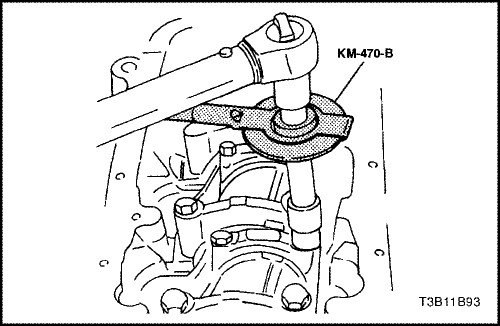
Tighten
Tighten the connecting rod bearing cap bolts to 35 N·m (26 lb-ft). Using the KM-470-B angular torque gauge, tighten the connecting rod bearing cap bolts an additional 45° plus 15°.
8. Remove the connecting rod bearing caps.
9. Measure the width of the flattened plastic gauging wire using a ruler. (Plastic calibration wire is available for different tolerances).
10. Check the bearing clearances for permitted tolerances. Follow step "Engine Specifications" in this section.
[Original version of the article on the website «CHEVYMAN.RU»]