Contents: Removal procedure ↧ Installation procedure ↧
Necessary equipment
- EN-48243 Engine assembly removal/installation rack
- EN-48244 Rack bracket for engine assembly removal/installation
Removal procedure
1. Remove the fuel pump fuse.
2. Start the engine. After the engine stops, crank the engine for 10 seconds to relieve pressure in the fuel system.
3. Drain the engine oil.
4. Drain the engine coolant. See Section 1D2, Engine Cooling System - FAM II 2.4D.
5. Drain the power steering fluid.
6. Drain the transmission oil. See Section 5A, AISIN 55-51LE Automatic Transmission with Final Drive Assembly or Section 5B, Five-speed gearbox with final drive assembly (D33).
7. Discharge the air conditioning system, if equipped. Follow section 7B, Heating, Ventilation, and Air Conditioning Systems Control.
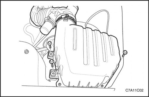
8. Disconnect the intake air temperature (IAT) sensor connector.
9. Remove the screw from the decorative engine cover.
10. Disconnect the breather hose and the positive crankcase ventilation hose from the cylinder head cover.
11. Remove the air cleaner assembly. See "Air filter assembly" in this section.
12. Remove the resonator from the electronic throttle body.
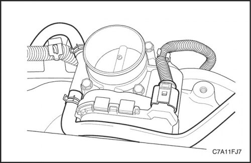
13. Disconnect the upper radiator hose from the thermostat.
14. Disconnect the lower radiator hose from the coolant pipe.
15. Disconnect the coolant hoses from the electronic throttle body.
16. Disconnect the expansion tank hose from the cylinder block.
17. Disconnect the heater outlet hose from the coolant pipe.
18. Disconnect the heater inlet hose from the cylinder head.
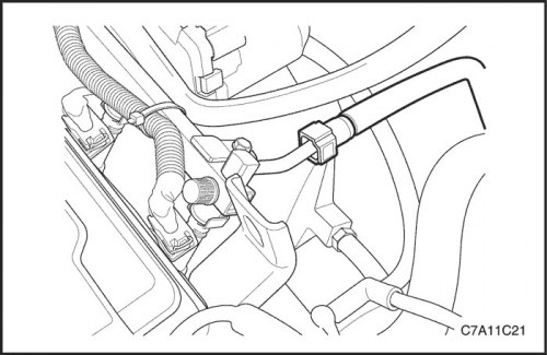
19. Disconnect the fuel line from the fuel rail.
20. Disconnect the power steering return hose and the pressure hose from the power steering pump. See section 6A, Power Steering System.
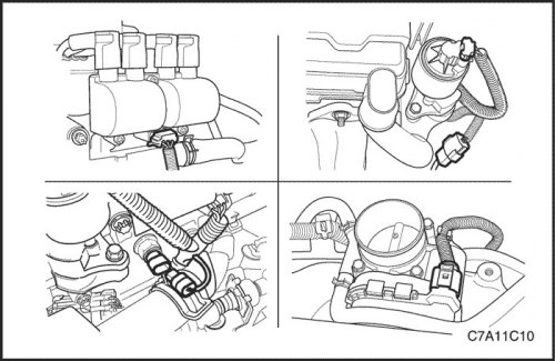
21. Disconnect all necessary electrical connectors, namely the air conditioner pressure sensor, exhaust gas recirculation valve, direct ignition system, coolant temperature sensor, electronic throttle control system, oxygen sensor, crankshaft position sensor, camshaft position sensor, manifold absolute pressure sensor, fuel injector, electronic engine control controller (ECM), knock sensor, alternator, starter terminal, etc.
22. Remove the ground terminals from the starter, intake manifold and cylinder block.
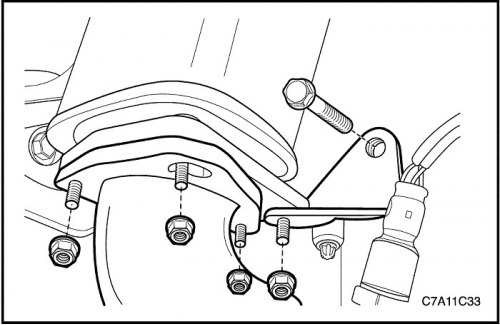
23. Remove all unnecessary parts and disconnect all connectors and cables from the transaxle assembly. See Section 5A, AISIN 55-51LE Automatic Transmission with Final Drive Assembly or Section 5B, Five-speed gearbox with final drive assembly (D33).
24. Disconnect all necessary vacuum lines, including the brake booster vacuum hose.
25. Remove the air conditioning compressor. Follow section 7B, Heating, Ventilation, and Air Conditioning Systems Control.
26. Disconnect the engine electrical wires from the engine.
27. Unscrew the nuts securing the catalytic converter to the exhaust pipe.
28. Remove the bolt and nut from the exhaust pipe mounting bracket.
29. Remove the exhaust pipe from the catalytic converter. See Section 1G2, Exhaust System - FAM II 2.4D.
30. For vehicles with permanent all-wheel drive: remove the propeller shaft. See Section 3B, Rear Drive Axle.
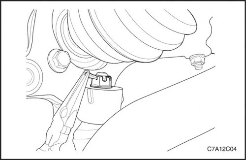
31. Disconnect the stabilizer bar mount. See Part 2D. Rear suspension.
32. Disconnect the tie rod end connection. See Part 2D. Rear suspension.
33. Disconnect the steering rod connection. See Part 2D. Rear suspension.
34. Remove the left and right axle shafts. See Section 3A, Automatic Transmission with Final Drive Assembly, Drive Axle or Section 3B, Manual gearbox with final drive assembly, Drive axle.
35. Remove the intermediate shaft of the power steering gear. See section 6C, "Power Steering".
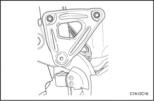
36. Loosen the support bracket retaining bolts. See section 2C, "Front Suspension".
37. Loosen the support mounting bolts.
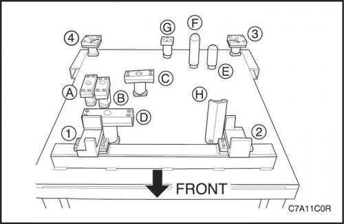
Caution: Make sure that all components of the EN-48243 Engine Assembly Removal/Installation Rack are aligned exactly with the EN-48244 Bracket as shown in the figure.
- 1~4: Support bracket
- A: Diesel engine oil pan bracket
- b: FAM II 2.4D Engine Oil Pan Bracket
- c & d: HFV6 3.2L Engine Oil Pan Bracket
- E: Bracket of manual transmission with final drive assembly
- F: Automatic transmission bracket with final drive assembly
- G: Transfer case bracket (M/T and A/T)
- H: Transaxle Mount Bracket (M/T and A/T)
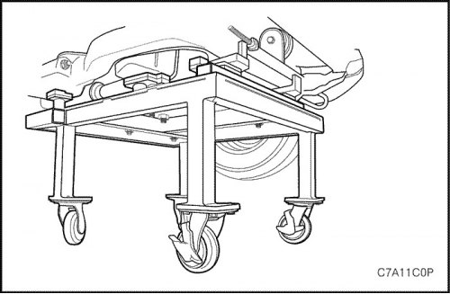
Caution: Lower the vehicle sufficiently to relieve the load on the engine mount and the transmission assembly, otherwise suspension damage and rack/rack bracket failure may occur.
38. Lower the vehicle and place the engine assembly on the EN-48243 Engine Assembly Rack with EN-48244 Rack Bracket until it rests.
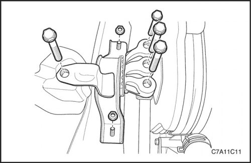
39. Remove the engine mount assembly. See "Engine mount assembly" in this section.
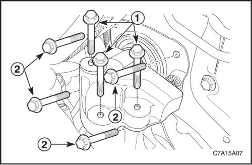
40. Remove the transmission mount assembly with the final drive assembly. See "Gearbox suspension with final drive assembly" in this section.
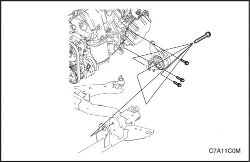
Caution: Make sure all wires, connectors and hoses are disconnected from the engine and transaxle assembly.
41. Raise the vehicle to freely remove the engine and gearbox with the final drive assembly.
42. Install a lifting device on the engine support bracket and raise the engine assembly to remove load from the front and rear suspension of the transaxle assembly.
43. Remove the front transmission suspension with the final drive assembly from the support. See "Front suspension of the gearbox with the main gear assembly" in this section.
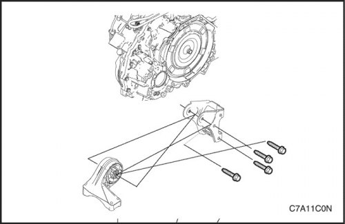
44. Remove the rear suspension of the gearbox with the final drive assembly from the support. See "Rear suspension of the gearbox with the main gear assembly" in this section.
45. Raise the engine assembly and remove the support from the engine and gearbox assembly.
46. Separate the cylinder block from the gearbox with the final drive assembly as follows.
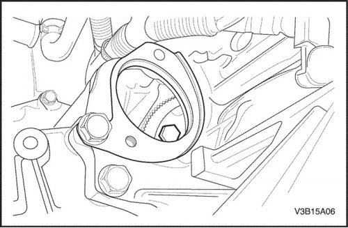
- Remove torque converter bolts.
- Loosen the mounting bolts connecting the gearbox with the final drive assembly to the engine cylinder block.
- Loosen the mounting bolts connecting the oil flange to the gearbox with the final drive assembly.
- Loosen the starter mounting bolts.
Installation procedure
1. Install the torque converter mounting bolts.
Tighten
Tighten the torque converter bolts to 45 Nm (33 ft·lbs).
2. Install the gearbox with the final drive assembly onto the engine cylinder block.
Tighten
Tighten the gearbox housing bolts with the final drive assembly to 75 N·m (55 ft·lbs).
Tighten the oil pan flange mounting bolts to the gearbox assembly with the final drive to a torque of 50 N·m (37 ft·lbs).
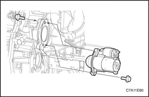
3. Install the starter mounting screws.
Tighten
Tighten the mounting bolt connecting the starter to the engine cylinder block to a torque of 75 N·m (55 ft·lbs).
Tighten the mounting bolt connecting the gearbox to the final drive assembly with the starter to a torque of 75 N·m (55 ft·lbs).
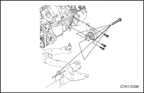
Caution: Ensure that all components of the EN-48243 Engine Assembly Removal/Installation Rack are aligned precisely with the EN-48244 Rack Bracket.
4. Install the engine and gearbox with the final drive assembly on the support.
Caution: Before tightening the front transmission mount clamp bolt, move the engine assembly back and forth or side to side to ensure proper installation.
5. Install the front suspension unit of the gearbox with the final drive assembly.
Tighten
Tighten the front transmission mount retaining bolts to 50 N·m (37 ft·lbs).
Tighten the front transmission suspension tie bolt to the support with a torque of 90 N·m (66 ft·lbs).
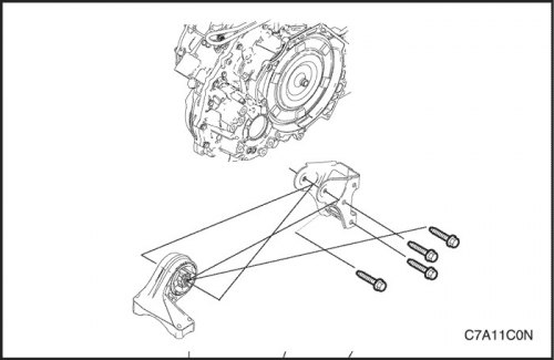
Caution: Before tightening the rear transmission mount clamp bolt, move the engine assembly back and forth or side to side to ensure proper installation.
6. Install the rear suspension of the gearbox with the final drive assembly onto the engine cylinder block.
Tighten
Tighten the rear transmission suspension mounting bolts with the final drive assembly to a torque of 90 N·m (66 ft·lbs).
Tighten the rear suspension tie bolt of the gearbox with the final drive assembly to the bracket with a torque of 90 N·m (66 ft·lbs).
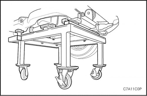
7. Raise the car.
8. Lower the vehicle and place the engine and gearbox assembly with the final drive connected to the support on the EN-48243 Engine Assembly Rack with EN-48244 Rack Bracket in the vehicle.
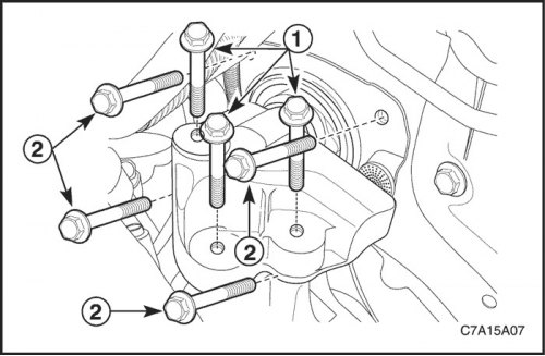
9. Install the gearbox mount with the final drive assembly. See "Gearbox suspension with final drive assembly" in this section.
Tighten
Tighten the transmission mount assembly lock bolts to 37 N·m (27 ft·lbs).
Tighten the gearbox assembly mounting bracket locking bolts to 50 N·m (37 ft·lbs).
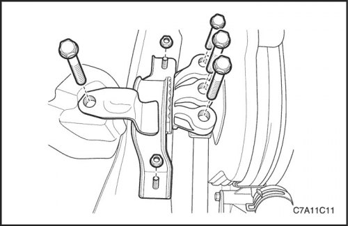
10. Install the engine mount assembly. See "Engine mount assembly" in this section.
Tighten
Tighten the engine mount frame side bracket locking bolt to 100 Nm (74 ft·lbs), and nuts with a torque of 90 Nm (66 ft·lbs).
Tighten the engine mount adapter retaining bolts to 50 Nm (37 ft·lbs).
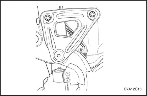
11. Remove the EN-48243 engine assembly removal/installation rack with the EN-48244 rack bracket from the vehicle.
12. Install the mounting bolts that connect the support to the body. See Section 2C, "Front Suspension". Section 2C, Front Suspension.
Tighten
Tighten the support mounting bolts to 155 Nm (114 ft·lbs).
13. Install the strut bracket retaining bolts. See Section 2C, Front Suspension. Section 2C, Front Suspension.
Tighten
Tighten the support bracket bolts to 50 Nm (37 ft·lbs).
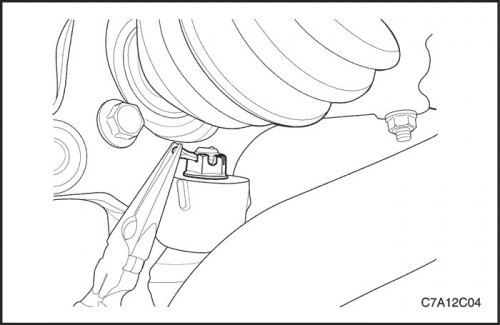
14. Install the power steering intermediate shaft. See section 6C, "Power Steering".
15. Install the left and right axle shafts. See Section 3A, Automatic Transmission with Final Drive Assembly, Drive Axle or Section 3B, Manual gearbox with final drive assembly, Drive axle.
16. Install the steering rod connection. See Part 2D. Rear suspension.
17. Install the tie rod end connection. See Part 2D. Rear suspension.
18. Install the stabilizer bar. See Part 2D. Rear suspension.
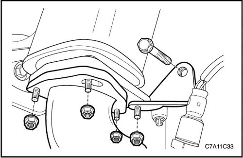
19. Install the exhaust pipe onto the catalytic converter. See Section 1G2, Exhaust System - FAM II 2.4D.
Tighten
Tighten the nuts securing the catalytic converter to the exhaust pipe to a torque of 40 N·m (30 ft·lbs).
Tighten the bolt and nut of the exhaust pipe mounting bracket to 40 N·m (30 ft·lbs).
20. For vehicles with permanent all-wheel drive: install the propeller shaft. See Section 3B, Rear Drive Axle.
21. Install the engine wiring harness onto the engine.
22. Connect all necessary vacuum lines, including the brake booster vacuum hose.
23. Connect the ground clamps.
24. Connect all necessary electrical connectors.
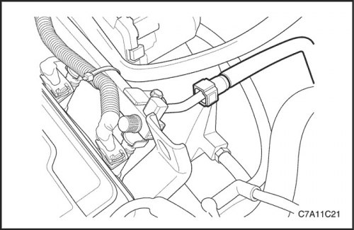
25. Connect the power steering hoses to the power steering pump. See section 6C, "Power Steering".
26. Connect the fuel supply line to the fuel rail.
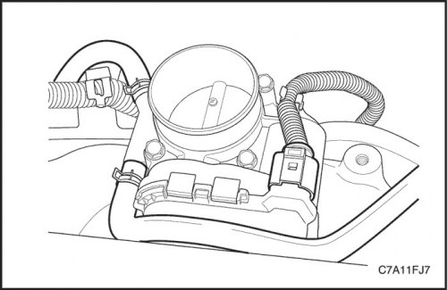
27. Connect the heater inlet and outlet hoses to the cylinder head.
28. Connect all necessary cooling system hoses to the electronic throttle body, thermostat, coolant pipe and engine block.
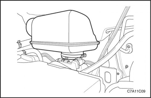
29. Install the resonator into the electronic throttle body.
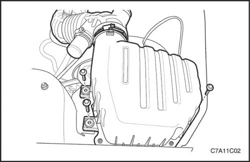
30. Install the air cleaner assembly. See "Air filter assembly" in this section.
31. Install the breather hose and positive crankcase ventilation hose on the cylinder head cover.
32. Connect the intake air temperature (IAT) sensor connector.
33. Install the decorative engine cover.
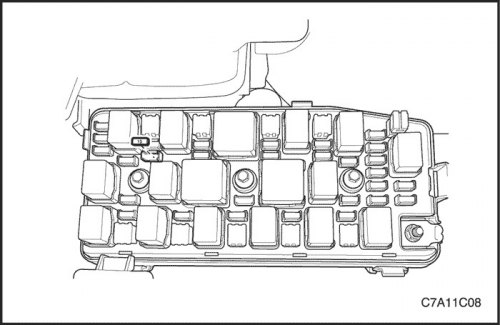
34. Install the fuel pump fuse.
35. Fill the crankcase with engine oil.
36. Fill the engine cooling system. See Section 1D2, Engine Cooling System - FAM II 2.4D.
37. Refill the power steering system and bleed the system. See Section 6A, Power Steering System
38. Refill the air conditioning refrigeration system, if equipped. Follow section 7B, Heating, Ventilation, and Air Conditioning Systems Control.