


Necessary equipment
J–8037 Universal Piston Ring Compressor
J–8087 Cylinder Bore Gauge
KM-427 Piston Ring Maintenance Kit
KM-470-B Angular Torque Indicator
Removal procedure
1. Remove the cylinder head with the intake and exhaust manifold attached. Follow step "Cylinder head and gasket" in this section.
2. Remove the oil pan. Follow step "Oil pan" in this section.
3. Remove the oil suction pipe and sealing ring.
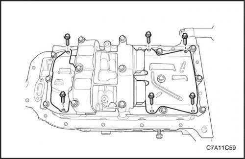
4. Remove the oil pan.
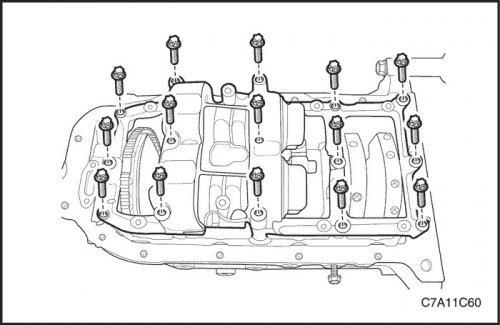
5. Remove the crankshaft balancer assembly. See "Crankshaft balancer assembly" in this section.
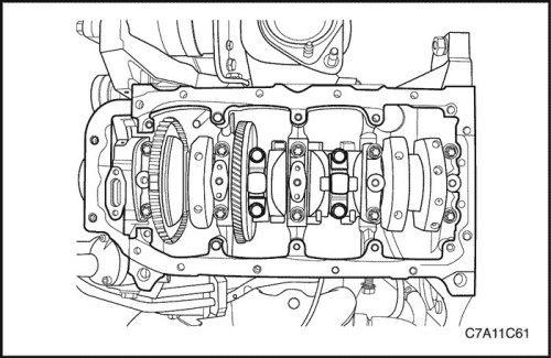
6. Set the piston to the bottom of the piston stroke.
7. Mark the position of the connecting rod head.
8. Remove the connecting rod head bolts.
9. Remove the connecting rod head and lower connecting rod bearing.
10. Remove the upper connecting rod bearing.
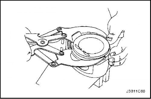
Caution! Handle the cylinder with care. Worn piston rings are sharp and can cause injury.
11. Remove the piston.
12. Expand the piston rings using the J-8037 Universal Piston Ring Compressor.
13. Remove the piston rings.
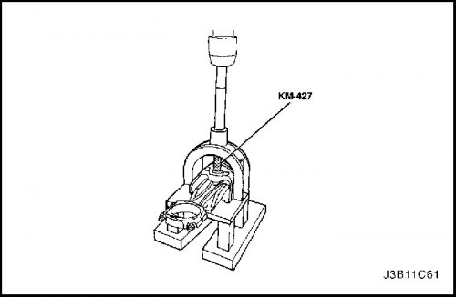
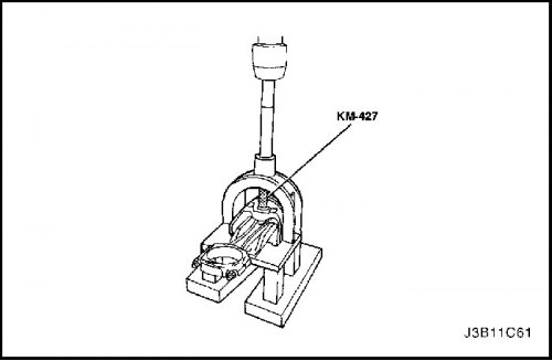
14. Remove the piston pin from the piston and connecting rod assembly using the KM-427 piston ring service kit.
15. Separate the piston from the connecting rod.
Verification procedure
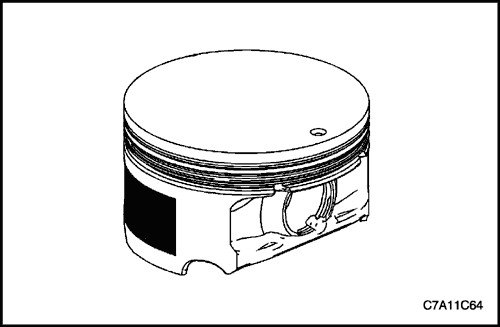
1. Inspect the pistons for the following faults.
- Are there any eroded areas on the piston crown?
- Are the piston pin holes and piston pins worn out?
- Is the piston skirt coating scratched or damaged?
- Are the ring grooves cracked, dented or scored which could cause binding?
- Are the bridges between the piston ring grooves warped or worn out?
2. Replace pistons that show any signs of damage or excessive wear.
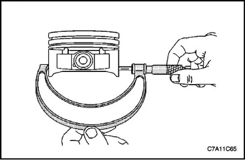
3. Measure the piston width using the following procedure.
- Using an outside micrometer, measure the piston width on the piston bearing surface, perpendicular to the piston pin centerline.
- Compare the piston measurement result with its size in the original cylinder, subtracting the piston width from the cylinder diameter.
- If the clearance obtained as a result of measurement is greater than the standard, and the cylinder bore is within the standard, it is necessary to replace the piston.
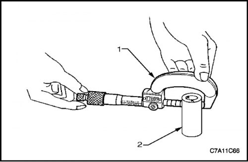
4. Measure the clearances between the piston pin bore and the piston pin (2) using the following procedure.
- There should be no carbon deposits or scoring in the piston pin holes or on the pins.
- To measure the piston pins in the areas of contact surface with the pistons, use an external micrometer (1).
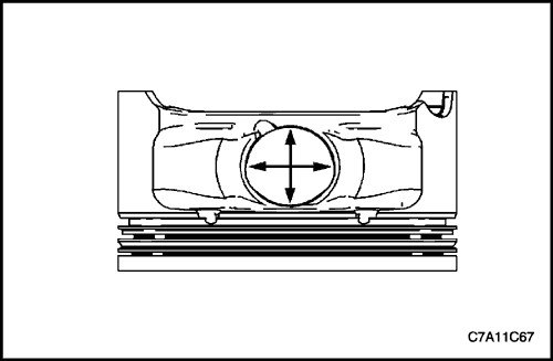
- Using an inside micrometer, measure the piston pin bore (1). Compare the result with the piston pin diameter and the clearance between the piston pin and the piston pin bore. Follow step "Engine Specifications" in this section.
- If the gap is too large, determine which part does not meet the standard and replace it if necessary.
- Replace the piston if any of its dimensions are not within specification.
- If the new piston does not meet the standard clearance, the cylinder can be bored by 0.25 mm. Only one repair size of pistons and rings is provided for maintenance.
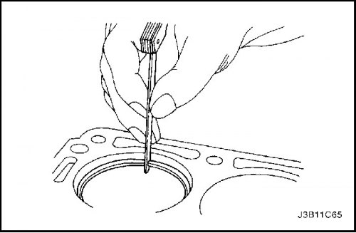
5. Measure the piston ring end clearance using the following procedure.
- There should be no carbon deposits or scoring in the piston pin holes or on the pins.
- Place the piston ring (1) in the bore in which it will move, approximately 25 mm below the surface of the cylinder block plate. Make sure that the ring is installed at right angles to the cylinder bore by setting the position of the ring using the piston head.
- Measure the piston ring end clearance using clearance gauges (2).
- If the gap exceeds the specified standards, the piston rings must be replaced.
- Repeat the procedure for all piston rings.
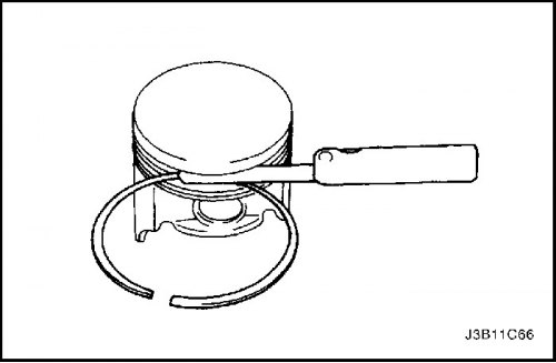
6. Measure the piston ring side clearance using the following procedure.
- Insert the piston ring (1) completely into the piston groove. If the ring is seized by the piston groove, file the groove with a fine file. If the ring is seized by deformation of the piston ring, the ring must be replaced.
- After installing the piston ring on the piston, check the gaps in several places using feeler gauges (2).
- Compare the measurements with the piston ring side clearance. Follow step "Engine Specifications" in this section.
- If the gap is greater than specified in the standards, it is necessary to replace the piston rings.
- If the new ring does not reduce the gap and achieve the standard, then a new piston must be installed.
- If the new piston fails to achieve the standard clearance, the cylinder block size must be increased by 0.25 mm. There is only one oversize piston and ring available for service.
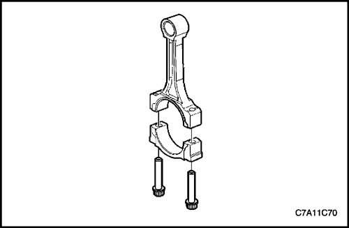
7. Check the connecting rods as follows.
- Check that the connecting rod is not twisted or bent.
- Check the connecting rod cap for dents or damage due to possible interference.
- Check the connecting rod bearing support surface for scratches or wear marks.
- If there are minor scratches and abrasion marks on the connecting rod holes, the holes should be cleaned around the circumference using fine sandpaper.
- Temporarily install the old bolts. They must be replaced during final installation.
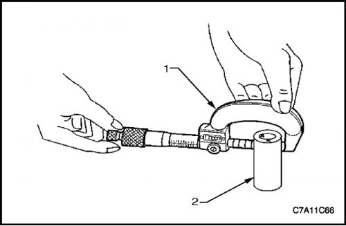
8. Measure the clearance between the connecting rod piston pin bore and the piston pin using the following procedures.
- Using an external micrometer (1), take two measurements of the piston pin (2) in the connecting rod contact area.
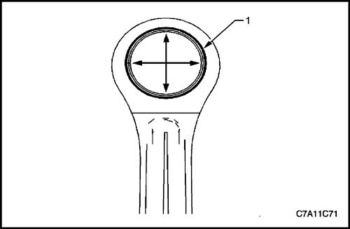
- Using an inside micrometer, measure the piston pin bore of the connecting rod (1).
- Subtract the piston pin diameter from the piston pin bore size.
- Compare gap measurements. Follow step "Engine Specifications" in this section.
- If the clearance is too large, replace the piston pin. If a new pin does not solve the clearance problem, the connecting rod will need to be replaced.
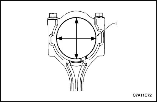
9. Measure the connecting rod main bearing bore (1) using the following procedures.
- Using an inside micrometer, measure the connecting rod main bearing bore.
- Compare the hole measurements. Follow the step "Engine Specifications" in this section.
- If the hole does not match the standard, replace the connecting rod. Do not repair the connecting rod.
10. Check the cylinder block plate surface for flatness using a straightedge and feeler gauge. Follow step "Engine Specifications" in this section.
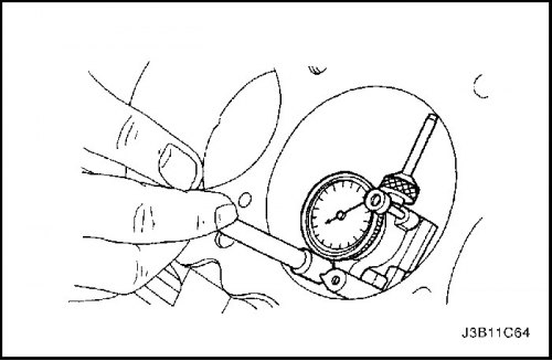
11. Check the bearing bore for concentricity and alignment using the J-8087 Cylinder Bore Gauge, Follow step "Engine Specifications" in this section. If the bearing bore is outside the normal range, replace the cylinder block.
12. Check the cylinder block bore for wear, runout and taper using a bore gauge. Follow step "Engine Specifications" in this section.
13. Check the cylinder block bore polish. Lightly hone the cylinder bore if necessary.
Installation procedure
Important: To facilitate installation of the piston pin, the connecting rod should be heated to 280°C. Only heat the upper connecting rod. Use commercially available hot-melt paint to determine the correct temperature. When the hot-melt paint changes color from black to green, the temperature has reached the required value for installation.
1. Align the notch on the piston and connecting rod so that the correct side faces the front of the engine.
2. Insert the piston pin guide into the piston and connecting rod.
3. Lubricate the piston with non-additive oil.
4. Insert the piston pin into the opposite side of the piston.
5. Install the piston pin into the piston and connecting rod assembly using the KM-427 piston ring service kit.
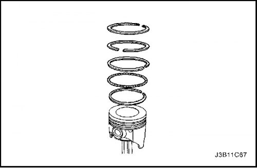
6. Select a set of new piston rings.
7. Install the oil scraper ring, expander, and then the second oil scraper ring on the lower groove of the piston ring.
8. Install the second compression ring onto the middle ring groove of the piston.
9. Install the upper compression ring onto the upper ring groove of the piston.
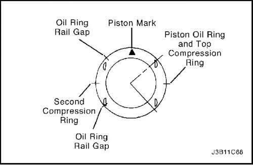
10. Use a piston ring expander to install the piston rings. Do not expand the piston rings beyond the limits required for installation.
11. Position the oil scraper rings, oil scraper ring guide gaps, second compression ring and top compression ring offset from the notch on the top of the piston.
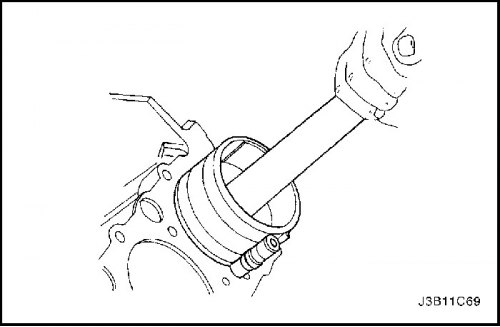
12. Lubricate the cylinder wall and piston rings with pure motor oil.
13. Install the piston ring using the J-8037 piston ring compressor and a wooden handle. Guide the lower part of the connecting rod to prevent damage to the crankshaft journal.
14. Install the connecting rod head and bearings. Follow step "Main and connecting rod bearings - calibrated plastic wire" in this section.
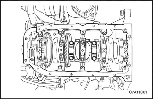
15. Install the connecting rod head bolts.
Tighten
Tighten the connecting rod bearing cap bolts to 35 Nm (26 ft·lbs). Using the KM-470-B angular torque indicator, tighten the bolts one turn per 45 degrees plus one turn per 15 degrees.
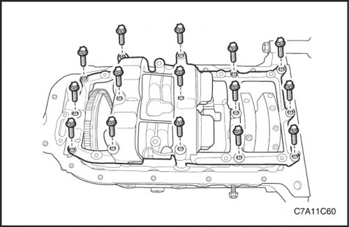
16. Install the crankshaft balancer assembly.
Tighten
Tighten the crankshaft balancer assembly bolts to 20 Nm (15 ft·lbs) and turn the bolts another 45° using the KM-470-B angular torque indicator.
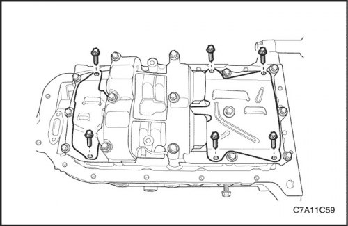
17. Install the oil pan scraper bolts.
Tighten
Tighten the oil pan scraper bolts to 8 N·m (71 lbs.in).
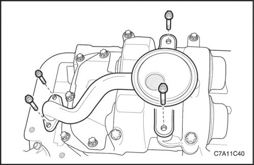
18. Install the oil suction pipe with the sealing ring.
Tighten
Tighten the oil suction pipe bolts to 8 Nm (71 lbs.in).
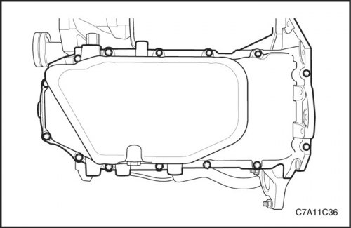
19. Install the oil pan. Follow the step "Oil pan" in this section.
20. Install the cylinder head with the intake and exhaust manifold attached. See "Cylinder Head and Gasket" "Cylinder head and gasket" in this section.
(The original source of the article is the website «chevyman»)