
Contents: Removal ↧ Analysis of the condition of engine… ↧ Installing piston rings ↧ Installation ↧ Checking the oil clearance of… ↧ Final installation ↧
Removal
Note: Before removing the connecting rod and piston group components, it is necessary to dismantle the cylinder head and the oil pan (see chapter 2A).
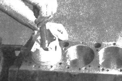
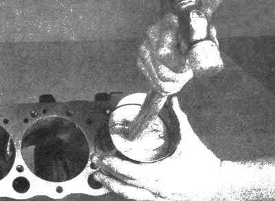
1. Using your fingernail, check for the presence of oil in the cylinder (about 6 mm from the top) comb, which can be in the upper position of the piston ring. If the presence of ridges formed as a result of wear of cylinder surfaces and accumulation of carbon deposits is confirmed, completely remove the defects using a special device (see illustration). Follow the instructions for using the tool. Attempting to remove connecting rod and piston components without first removing the existing ridges may result in damage to the pistons.
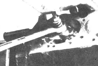
9.1 Remove the ridge located at the top of the cylinders using a special reamer - this must be done before removing the pistons
2. After removing the ridges that have formed, turn the cylinder block upside down to gain access to the crankshaft.
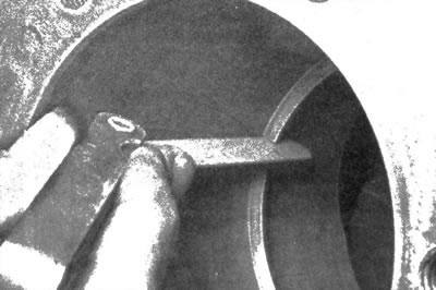
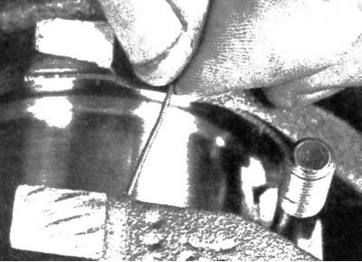
3. Before removing the main bearing caps and connecting rods, check the axial play of the connecting rods using a set of feeler gauges for measuring clearances. Insert feeler gauges between the end surface of the lower head of the first connecting rod and the crankshaft cheek until you find a feeler gauge that slides in this gap with little resistance (see illustration). Perform the described operation on each connecting rod. The axial play will correspond to the thickness of the feeler gauge. Check with your auto repair shop for the permissible limit for axial play (as a rule, it lies within the range of 0.13 - 0.38 mm). If the axial clearance exceeds the limit, it is necessary to replace the connecting rods. When installing new connecting rods (crankshaft), the axial clearance may be less than the established limit. In this case, it is necessary to subject the connecting rods to mechanical processing. If necessary, contact a car repair shop for advice.
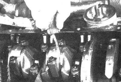
9.3. Check the connecting rod axial play using a set of feeler gauges
Analysis of the condition of engine bearings
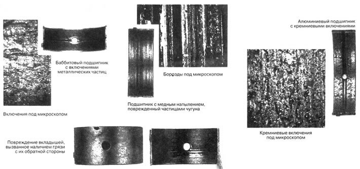
Pollution
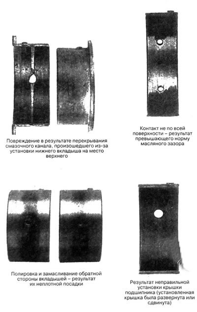
Incorrect assembly
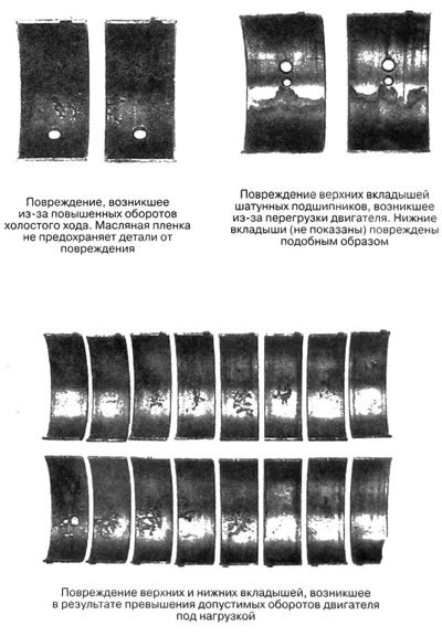
Reboot
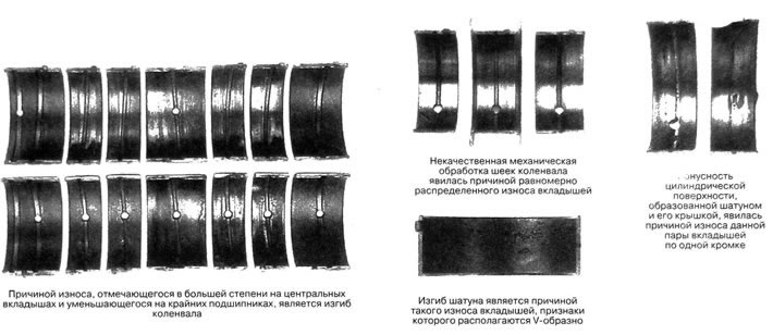
Incompatibility of provisions
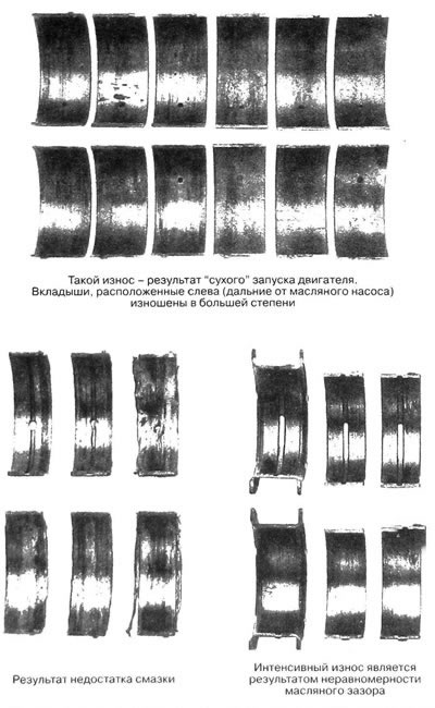
Lack of lubrication
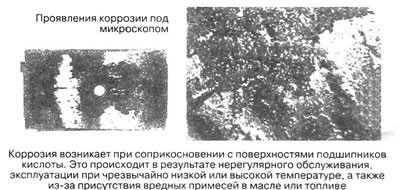
Corrosion
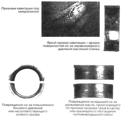
Lack of lubrication
4. Make sure that the connecting rods and bearing caps have identification marks. If the marks are missing or difficult to see, apply them using a felt-tip pen or paint, marking each connecting rod and cover (for example, 1, 2, 3, etc., depending on the cylinder number).
Caution: Do not use a punch and hammer to mark the connecting rods as this method may damage them.
5. Loosen the connecting rod cap bolts one by one, one half turn at a time, until you can remove them by hand.
Note: During subsequent assembly, be sure to install new connecting rod bearing cap bolts. Do not discard the old bolts immediately after removing them, as they should be used when checking the connecting rod bearing oil clearance.
6. Remove the cover and bearing shell of the first connecting rod. Do not allow the insert to fall out of the lid.
7. Remove the bearing shell and push the connecting rod/piston out through the top of the cylinder. Push the connecting rod by pressing the handle of a wooden or plastic hammer against the working surface of the bearing. If resistance is felt during the pushing process, make sure the ridge at the top of the cylinder is completely removed.
8. Carry out the described procedure on the remaining cylinders.
9. After removing the connecting rod and piston group, reassemble the caps and bearing shells with the corresponding connecting rods, tightening the cap mounting bolts by hand. Leave the old bearings in the connecting rods to prevent damage to the working surfaces until assembly begins.
10. The pistons/connecting rods are now ready for inspection and restoration in a workshop environment.
Installing piston rings
11. Before installing piston rings on pistons, measure the gaps of the cuts. It is assumed that the side clearances of the rings have been pre-checked.
12. Lay out the pistons/connecting rods and rings in a specific order that will allow the rings to be installed on the pistons and in the cylinders where the clearance measurements were taken.
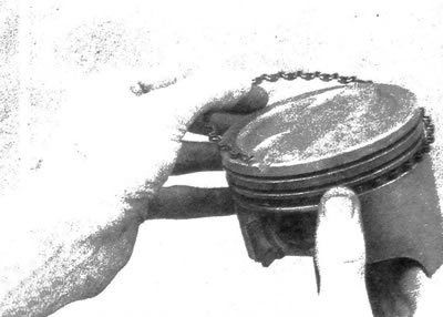
13. Insert the upper (first) ring into the first cylinder and, pushing it with the piston, position it perpendicular to the cylinder walls (see illustration). Move the ring to the base of the cylinder, to a position that corresponds to the bottom dead center of the piston.
9.13. When measuring the clearance, the ring should be positioned perpendicular to the cylinder walls (this is achieved by pushing the ring into the cylinder with the piston as shown in this illustration)
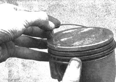
14. To determine the gap of the ring cut, insert feeler gauges into the cut until you select a feeler gauge whose width is equal to the size of the gap (see illustration). Such a probe should slide through the cut with little resistance. The gap of the compression ring should be within 0.25 - 0.50 mm, and the gap of the oil scraper ring should not exceed 0.76 mm. In case of discrepancy between the obtained and given values, make sure again that the rings are selected correctly. Contact the auto parts store where you purchased the rings to confirm that they are the correct type.
9.14. With the ring positioned perpendicular to the cylinder walls, measure the gap using a set of feeler gauges
15. If the ring gap is too small, it should be adjusted to normal, otherwise the ends may close during engine operation, which will lead to serious damage to the power unit. If necessary, increase the gap by carefully filing the ends of the ring with a fine-grain file. Secure the file in a vice with soft pads, position the ring so that the file is in the gap and, slowly moving the ring, widen the gap to the required value. Perform filing by moving the ring only in the direction of the vice, from the outer end of the file (see illustration).
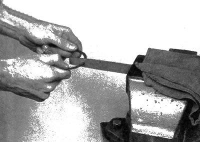
9.15 If the gap is too small. it should be brought back to normal. Secure the file in a vice and file the ends of the piston ring
16. If the ring gap exceeds the norm by only 1 mm, then such a deviation should not be considered critical. Again, make sure you have selected the correct rings.
17. Repeat the described procedure with the remaining rings of the first cylinder and with each ring in the remaining cylinders. Remember to maintain proper alignment of rings, cylinders and pistons.
18. After checking and adjusting the gaps, you can begin installing the rings on the pistons.
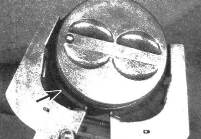
19. As a rule, the oil scraper ring is installed first (in the lower position on the piston), which consists of three parts. Install the expander/seal into the groove (see illustration). If a dowel pin is provided, make sure it fits into the hole in the piston ring groove. Then install the top part of the ring using the same technique (see illustration). Do not install the oil scraper ring components using a special tool, as this may cause damage to the components. Instead, place one end of the component into the groove between the seal and the base of the groove and press firmly, running your finger around the piston and guiding the ring component into the groove. Then install the bottom component in the same way.
9.19a. Install the expander/seal into the groove
9.19b. Do not install oil scraper ring components using a special tool
20. After installing the oil scraper ring, make sure that the upper and lower components can be rotated freely in the groove.
21. Then install the second (middle) compression ring. Typically, it will have a mark on it that should face up. Do not confuse the top and middle compression rings as they have different cross-sections.
Note: Follow the instructions supplied with new piston ring sets. The principles of installing rings from different manufacturers may differ.
22. Make sure that the mark is located on the upper side of the ring, then install the ring into the middle groove on the piston using a special tool (see illustration). Do not spread the ring more than necessary to fit into the piston groove.
9.22. Install the second and first (upper) rings using a special tool. Make sure the ring marks are facing up
23. Install the upper compression ring in a similar manner. Make sure the ring mark is positioned correctly. Do not confuse the first and second compression ring.
24. Perform the above procedures with the remaining pistons and rings.
Installation
25. Before installing pistons/connecting rods, make sure the cylinder walls are absolutely clean. The procedure is carried out after preliminary installation of the crankshaft and rounding of the upper edges of the cylinders by grinding.
26. Remove the first connecting rod cover (please note the marks made during removal). Remove the old bearing shells and wipe the bearing surface on the connecting rod and its cap with a clean (lint-free) cloth. Work surfaces must be kept spotlessly clean.
Checking the oil clearance of connecting rod bearings
27. Clean the back of the new upper bearing shell, then install it into the connecting rod.
28. Make sure that the bearing shell protrusion and the connecting rod recess are aligned. Do not seat the bearing shell with a hammer, and do not allow the working surface of the shell to be damaged. At this stage, the liner is not lubricated during installation.
29. Clean the back of the other bearing shell and install it into the connecting rod cap. Make sure that the protrusion of the insert and the recess of the cover are aligned. At this stage, the liner is not lubricated during installation. It is extremely important to ensure that the mating surfaces of the bearing, connecting rod and cap are perfectly clean after assembly.
30. Arrange the piston ring cuts in the order shown (see illustration).
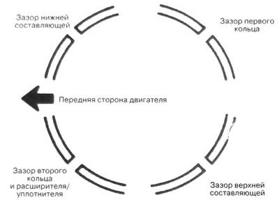
9.30. Location of ring cuts
31. Lubricate the piston and rings with assembly oil. Install a ring compressor on the piston. The piston should protrude from the fixture by approximately 6 mm so that it can be guided into the cylinder. The rings should be compressed until their surface is aligned with the surface of the piston skirt.
32. Turn the crankshaft, bringing the first connecting rod journal to the position corresponding to the piston bottom dead center (BDC), then apply a layer of engine oil to the cylinder wall.
33. Position the mark on the piston towards the front side of the engine (in the direction of the chain), carefully insert the piston and connecting rod assembly into the first cylinder and press the lower edge of the ring compressor against the cylinder block.
34. Tap the top edge of the ring compression tool to ensure that it fits tightly against the block around the entire circumference of the cylinder.
35. Gently tap the bottom of the piston with the wooden handle of the hammer (see illustration), seating the connecting rod on the crankshaft journal. The piston rings can pop out of the ring compressor just before they enter the cylinder, so it should be pressed lightly against the block. Perform the procedure in a measured rhythm, and if resistance to the movement of the piston in the cylinder occurs, stop immediately. Before continuing work, be sure to determine the cause of the jam. Never force the piston into the cylinder, as this can cause damage to the piston and/or its rings.
9.35 The piston can be inserted into the cylinder by gently tapping it with the wooden handle of a hammer
36. After installing the piston/connecting rod assembly, before finally installing the connecting rod caps, the oil clearances of the connecting rod bearings should be checked.
37. Cut strips of plastic indicator of suitable size (slightly shorter than the width of the connecting rod bearing shell) and place it on the first crankpin, parallel to the shaft axis (see illustration).
9.37. Place the indicator strips on the connecting rod journals parallel to the crankshaft axis
38. Clean the mating surface with the liner in the cover. Make sure that the timing marks on the cover and connecting rod are aligned (see illustration 9.4).
39. Tighten the old cover bolts to the specified torque.
Note: When tightening the connecting rod bolts, a thin-walled socket head should be used to avoid high torque error that may occur due to the head jamming between the bolt and the connecting rod cap. If the head jams, lift it slightly and remove it from the gap between the bolt and the cover. Do not rotate the crankshaft during this procedure.
40. Unscrew the bolts and carefully remove the connecting rod cover. Do not allow the plastic indicator section to shift. The cover bolts can now be discarded as new fasteners are always installed during final assembly.
Note: New connecting rod cap bolts MUST be installed.
41. Compare the width of the crushed section of the indicator with the scale diagram supplied with the indicator and determine the size of the oil gap (see illustration). The gap should be 0.025 - 0.05 mm. Check the value by consulting with the company station.
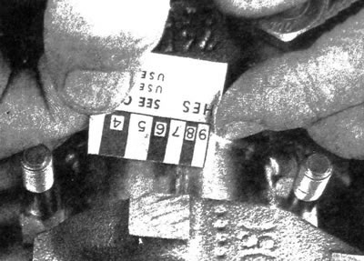
9.41. Compare the width of the crushed section of the indicator with the scale diagram and determine the size of the oil gap (to determine the gap, match the widest part); make sure that the gap was determined using the appropriate diagram - the indicator is equipped with an inch and metric scale
42. If the gap value is outside the required value, it should be assumed that the bearing size is incorrect (which means they need to be replaced). Before deciding to replace the bearings, make sure that there was no dirt or grease build-up when measuring the clearance between the bearing cap, rod and bearing surfaces. Also measure the crankshaft journal diameter. If the indicator widens at one end, the corresponding crankpin may be tapered. If the clearance still exceeds the required value, install bearings of reduced size.
Caution: When installing a new crankshaft, always install standard size connecting rod bearings.
Final installation
43. Carefully remove any remaining plastic indicator from the surfaces of the connecting rod journals and/or bearing shells. Scrape off any remaining indicator with your fingernail or the edge of a plastic card, being careful not to damage the working surfaces of the bearings.
44. Make sure the bearing surfaces are perfectly clean, then lubricate both bearing shells on each side with molybdenum or assembly oil. To gain access to the connecting rod bearing surface, the piston must be moved in the cylinder.
Caution: Install new bolts into the connecting rod caps. It is not acceptable to use old fasteners as they are stretched.
45. Place the connecting rod on the journal, install the cap and tighten the new bolts to the required torque. As before, tightening in this case is done in three stages.
46. Perform the described procedures with the remaining pistons/connecting rods.
47. Some important features should be noted:
- a) Before assembly, ensure that the reverse surfaces of the bearing shells, connecting rods and caps are absolutely clean.
- b) Make sure that the cylinders, pistons and connecting rods are aligned.
- c) The mark located on the piston should face forward.
- d) Lubricate the cylinder walls with clean engine oil.
- e) Lubricate the bearing surfaces when installing the connecting rod caps, after checking the oil clearances.
48. After installing the pistons/connecting rods, turn the crankshaft by hand to ensure that it rotates evenly and smoothly.
49. Finally, check the connecting rod axial play again.
50. Check that the axial clearance is within the norm by comparing the obtained values with the values given in the specifications. If the axial play was within the norm before disassembly, and the same connecting rods and crankshaft were installed during assembly, then the axial play should be within the same acceptable limits. When installing a new crankshaft and connecting rods, the axial clearance of the connecting rods may not comply with the norm. If the clearance is not within the norm, the connecting rods should be removed and taken to a workshop for mechanical processing.
(The original article can be found on the resource CHEVYMAN.ru)