
Contents: Removal ↧ Installation ↧ Checking the main bearing oil… ↧ Final installation of the crankshaft ↧
Removal
Note: Removal of the crankshaft is only possible after dismantling the engine. In this case, you should first remove the drive disk, crankshaft pulley, oil pan, drive chain, and pistons/connecting rods. Unscrew the mounting bolts and remove the rear oil seal holder from the cylinder block.
1. Before removal, check the axial play of the crankshaft. Install the gauge with a pointer indicator so that its rod touches the end surface of the shaft (see illustration).
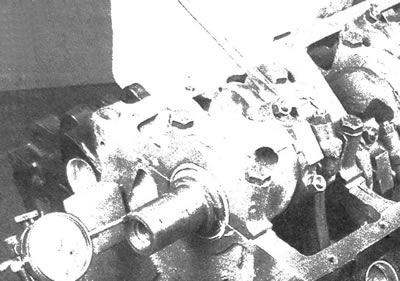
10.1. Checking the axial play of the crankshaft using a dial gauge
2. Move the crankshaft back as far as it will go and set the meter indicator to zero, then move the shaft forward as far as it will go and read the meter reading. The distance the crankshaft moves is its axial clearance. The clearance value should be 0.076-0.254 mm. If the clearance value exceeds this value, the thrust surfaces of the crankshaft should be inspected for wear. If the degree of wear of the thrust surfaces is acceptable, the excessive axial play of the shaft is eliminated by installing new main bearings.
3. If you don't have a gauge with an arrow indicator, you can use feeler gauges to measure gaps. Move the crankshaft forward as far as possible. By measuring the clearance between the crankshaft and the face of the main bearing thrust surface using feeler gauges, determine the axial clearance of the shaft (see illustration).
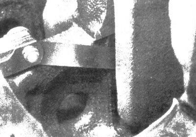
10.3. Checking the axial play of the crankshaft when measuring with a feeler gauge on the journal of the thrust bearing
4. Loosen the main bearing cap bolts one-quarter turn at a time until they can be removed by hand.
5. It is necessary to remove the reinforcing element, then check for the presence of location marks on the main bearing caps. If necessary, number the bearing caps starting from the front of the engine and mark each one with an arrow pointing forward. Remove the bearing caps. If the bearing shells remain in the caps, try to prevent them from falling out when removing them.
6. Carefully remove the crankshaft from the cylinder block. Since the shaft is quite heavy, it is recommended to have an assistant. With the bearing shells in the block and caps, install the caps and reinforcement and finger tighten the mounting bolts. Ensure that the main bearing caps are correctly positioned. The arrows on the lids should point forward.
Installation
7. Installing the crankshaft is the first and one of the most important stages of engine assembly. At this stage it is assumed that the cylinder block and crankshaft have been cleaned, inspected and, if necessary, rebuilt or repaired.
8. Install the engine with the base facing up.
9. Unscrew the mounting bolts and remove the reinforcing element and main bearing caps.
10. Remove the pre-installed main bearing shells from the cylinder block and covers. Wipe the bearing seats with a clean cloth. Ensure that the bearing seats are extremely clean, as this is essential for accurate oil clearance measurement.
Checking the main bearing oil clearance
11. Clean the backs of the new upper main bearing shells and install them in their proper locations in the cylinder block. Upper (installed in the block) the insert has a groove and a lubrication hole.
Caution: The oil holes in the cylinder block and upper bearing shells must be aligned.
Thrust bearings or washers are installed on the fifth journal of the crankshaft (when counting from the front). Clean the lower main bearing shells from the back side and place them on the corresponding cap journals. Make sure that the tabs on the bearing shells fit into the recesses in the covers or cylinder block. The upper liners, which have holes, are installed in the cylinder block, and the lower, solid ones are installed in the covers.
Caution: Do not install bearing shells with a hammer or damage the bearing surfaces. Do not use any lubricant during the installation process at this stage.
12. Clean the bearing mating surfaces on the cylinder block and on the crankshaft main journals with a clean, lint-free cloth.
13. If necessary, clean the crankshaft oil holes, as dirt from the holes may get onto the new bearings.
14. After thorough cleaning, carefully install the crankshaft into the cylinder block.
15. Before final installation of the crankshaft, the oil clearance of the main bearings should be checked.
16. Cut several pieces of plastic indicator of suitable size (the sections should be slightly shorter than the width of the main bearing shells).
17. Place one piece on each main journal parallel to the shaft axis (see illustration).
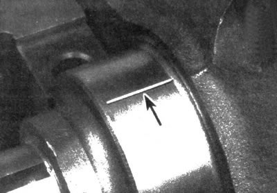
10.17. Place the indicator strips on the end of the journal parallel to the crankshaft axis
18. Clean the mating surfaces of the liners in the covers or lower crankcase. While holding the liners, install the covers or crankcase onto the crankshaft and cylinder block. Do not allow the plastic indicator sections to shift. Make sure the arrows on the installed main caps point forward, then install the reinforcement member.
19. Before installation, lubricate the threads of the old bolts with engine oil and tighten them with your fingers. Gradually tighten the bolts to the required torque, starting with the center fasteners and moving to the outer bolts. Do not allow the crankshaft to turn.
20. Unscrew the bolts in the reverse order of tightening and carefully remove the reinforcing element and main bearing caps. The covers must be removed in a strictly vertical direction. Do not allow the indicator strips to shift or the crankshaft to turn.
21. Compare the width of the crushed section of the indicator on each main journal with the scale diagram supplied with the indicator and determine the oil clearance value (see illustration). Make sure that the obtained clearance values are within the norm. Check the oil gap size by contacting the authorized service station.
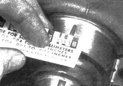
10.21. Compare the width of the crushed section of the indicator with the scale diagram and determine the size of the oil gap (to determine the gap, match the widest part); make sure that the gap was determined using the appropriate diagram - the indicator is equipped with an inch and metric scale
22. If the gap is not within the norm, it should be assumed that the bearing size is incorrect (which means they need to be replaced). Before deciding to replace the bearings, make sure that there was no dirt or grease build-up when measuring the clearance between the surfaces of the covers, cylinder block and bearings. If the indicator widens at one end, the main journal is tapered. If the gap exceeds the permissible limit, the bearing shells should be replaced with smaller size parts.
Caution: When installing a new crankshaft, be sure to use the correct size bearings.
23. Carefully remove any remaining plastic indicator from the surfaces of the main journals and/or bearing shells. Scrape off any remaining indicator with your fingernail or the edge of a plastic card, being careful not to damage the working surfaces of the bearings. Clean the oil holes if necessary.
Final installation of the crankshaft
24. Carefully remove the crankshaft from the cylinder block.
25. Clean the mating surfaces of the bearing shells in the cylinder block, then coat them with a thin, uniform layer of molybdenum disulfide-based grease or assembly oil. Make sure that the working and thrust surfaces of the thrust bearing are lubricated.
26. Make sure the crankshaft journal surfaces are clean and install it into the cylinder block.
27. Clean the mating surfaces of the bearing shells, then lubricate them. Clean the surfaces of the cylinder block and bearing caps.
28. Install the main caps and reinforcement.
29. Before installation, lubricate the bolt threads with engine oil and tighten them with your fingers.
30. Tighten the main bearing cap bolts to the specified torque (tightening should begin with the central bolts and move on to the outer fasteners).
31. The crankshaft axial play should be checked using a set of feeler gauges or a gauge with an arrow-type indicator. If the thrust surfaces of the crankshaft are not damaged or excessively worn, then after installing new bearings, its axial clearance should comply with the norm.
32. Turn the crankshaft manually to ensure that it rotates smoothly and evenly. The shaft rotation should occur with a torque of no more than 6 Nm (before installing pistons/connecting rods). If more torque is required to turn, determine the cause of this discrepancy.
33. Install the new rear crankshaft oil seal (see chapter 2A).