


Contents: Removal ↧ Installation ↧
Warning 1: The air conditioning system is under high pressure. Do not loosen the couplings or remove components without first discharging the system when contacting an authorized or specialized service station. When disconnecting the air conditioning system couplings, wear protective glasses or a mask.
Warning 2: Certain precautions must be observed when performing preventive inspection and maintenance of the fuel system. Work in well-ventilated areas and do not allow open flames or unshielded light bulbs in the work area. Avoid contact with gasoline on your skin; wear rubber gloves when working. If gasoline gets on your skin, wash it off with running water and soap. Wipe up any spilled fuel immediately and store the absorbent cloth where it cannot ignite. Before working on fuel system components, release residual pressure (see chapter 4). Have a class B fire extinguisher on hand and wear safety glasses or a mask.
Warning 3: The vehicles described in this manual are equipped with a Supplemental Restraint System (SRS), also known as an air bag system. Before carrying out work in the area where the elements of this system are located, it is necessary to disconnect its power supply, since accidental deployment of the airbags can result in serious injury (see chapter 12).
Removal
1. Contact a branded or specialized service station to discharge the air conditioning system.
2. Release residual pressure in the fuel system (see chapter 4). Disconnect the cable from the negative battery terminal.
3. Cover the fenders and the panel located under the windshield, then remove the hood cover (see chapter 11). There are special pads to protect the wings, but it is quite acceptable to use an old blanket or coverlet for this purpose.
4. Remove the air cleaner (see chapter 4). Drain the coolant.
5. To ensure proper connections during subsequent assembly, attach identification tags to vacuum and bleed hoses, electrical connectors and ground wires, and fuel lines that will be disconnected during engine removal, then disconnect them (see illustrations). If there is a possibility of confusion, make a sketch or photo of the engine compartment and clearly mark the hoses, tubes and wires on it. Disconnect the corresponding brackets from the engine and move the wiring harness aside.
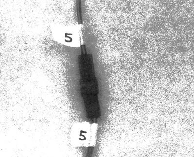
7.5a. Attach identification tags to wires before disconnecting
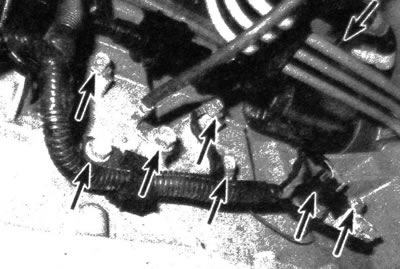
7.5b. Attached to the cylinder block are numerous grounding buses, brackets and electrical connectors (the left rear side of the engine is shown)
Note: Some wiring may be easier to disconnect when the vehicle is jacked up and supported on supports.
6. Mark and disconnect the cooling system hoses from the engine. It is also necessary to disconnect the heater hoses from the heat exchanger pipes located on the rear bulkhead of the engine compartment (see illustration).
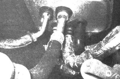
7.6. Disconnect the heater hoses from the heat exchanger
7. Remove the manifold absolute pressure (MAP) sensor.
8. Remove the throttle body (see chapter 4).
9. Disconnect from the condenser and filter drier (see warning at the beginning of this subsection).
10. Remove the radiator (see chapter 3).
11. Remove the drive belt (see chapter 1) and unscrew the bolts that secure the power steering pump (see chapter 10). Move the pump to the side and tie it with a piece of wire.
12. Unscrew and remove from the engine the nut that secures the bracket for the automatic transmission oil filling tube.
13. When performing the procedure on a four-wheel drive vehicle, it is necessary to disconnect the front axle wiring connector.
14. Remove the bolt that secures the automatic transmission hydraulic line bracket to the right of the engine, then move the lines away from the power unit.
15. Remove the PCM electronic unit (see chapter 6).
16. Raise the vehicle and support it on vertical stands. While performing the procedure under the vehicle, drain the engine oil (see chapter 1).
17. When performing the procedure on a four-wheel drive vehicle, it is necessary to remove the engine skid plate, front drive shafts and front propeller shaft (see chapter 8). Also, if necessary, remove the fuel tank protective plate.
18. Disconnect the exhaust pipe from the manifold (see chapter 2A) and pull it back.
19. Remove the service cover, mark the original relative position with the drive disk, then unscrew the torque converter bolts (see illustration).
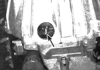
7.19 Mark the original relative positions of the torque converter and drive disc, then unscrew
20. Support the transmission with a floor jack.
Note: A wooden block must be placed between the jack and the gearbox housing.
21. Remove the gearbox jumper (see chapter 7A).
22. There are four bolts on top of the gearbox casing. To provide the space necessary to remove these bolts, the transmission must be lowered sufficiently. Disconnect the engine wiring harness from two of these bolts and remove all four bolts. After this, lift the box and install its crossbar, securing this element with only two bolts.
23. Remove the remaining gearbox casing bolts.
24. Unscrew the nuts of the lower engine mounts.
25. Lower the vehicle and remove the upper engine mount nuts. Support the transmission with a floor jack.
26. Connect the hoist chain to the mounting bracket located at the front of the engine (see illustration). Connect the other end of the chain to the rear right corner of the engine; unscrew the exhaust manifold bolt and, having installed another, longer bolt with the same diameter and thread pitch in its place, attach the chain to the cylinder head (see illustration).
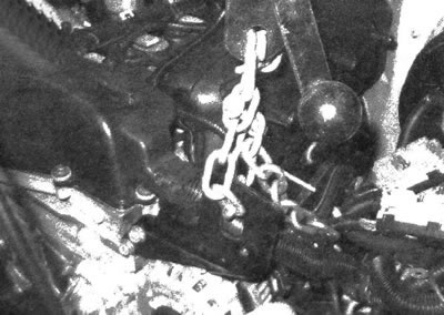
7.26a. Connect the winch chain to the mounting hook located at the front of the engine...
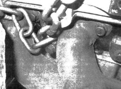
7.26b...and also to the right rear corner of the cylinder head (attach the chain with a bolt longer than the one you removed, add a washer if necessary). It is also acceptable to wrap the chain around one of the channels and secure it with a bolt.
Caution: DO NOT lift the engine by the intake manifold. Lift the power unit only by the cylinder head or block.
27. Roll the winch up and connect the chain to it. Tighten the chain, but do not lift the engine yet.
Warning: Do not allow any part of your body to come under an engine that is supported only by a winch or other lifting device.
28. Raise the engine slightly. Carefully push the motor forward to disconnect it from the transmission. Do not allow the torque converter to become disconnected from the transmission (secure the torque converter by placing a pair of clamps on the transmission housing). Slowly lift the engine and remove it from the engine compartment (see illustration). Make sure that no components become pinched during engine removal.
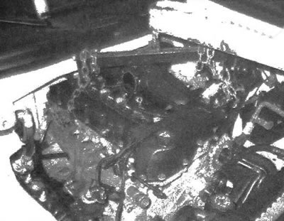
7.28 Pull the engine forward as far as possible to move it away from the transmission and also away from the body panel located under the windshield, then lift the engine so that it is disconnected from the car body
29. Remove the flywheel/drive plates and secure the engine to a stand.
Installation
30. Install the drive disc on the engine (see chapter 2A). Inspect and replace engine and transmission mounts if necessary.
31. Slowly lower the engine into the engine compartment. In this case, it is necessary to direct it towards the supports.
32. Connect the torque converter to the crankshaft as described in chapter 7A.
33. Install and securely tighten the bolts that secure the engine to the gearbox.
Caution: DO NOT pull the engine and transmission when tightening the bolts.
34. Install the remaining elements in the reverse order of removal.
35. If necessary, add coolant, engine and transmission oil, and power steering fluid (see chapter 1).
36. Start the engine and check that it is working properly and that there are no leaks of operating fluids. Install the hood and test drive the vehicle.
37. Contact a station of the appropriate profile to refill the air conditioning system and check it for leaks