
Compression check
1. The results of compression measurements will help determine the technical condition of engine parts (pistons, rings, valves, cylinder head gasket). By analyzing the results, it is possible to determine whether the loss of compression is caused by wear of piston rings, valves and their seats, or cylinder head gaskets.
Note: To perform a compression measurement, the engine must be warmed up to operating temperature. The battery must be fully charged.
2. Clean the areas around the spark plugs before removing them (use compressed air if possible, but a small brush or even a bicycle pump will also work). These measures are aimed at preventing dirt from entering the cylinders when performing compression measurements.
3. Remove the coils and spark plugs from the engine (see chapter 1 and 5).
4. Remove the fuel pump relay to de-energize its circuit (the relay is located in the fuse/relay box located in the engine compartment - see Chapter 4, Illustration 3.3).
5. Connect the compression tester to the first spark plug hole (see illustration).
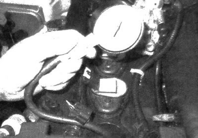
3.5. A compression gauge with an adapter screwed into the spark plug hole is preferable to a compression gauge that must be pressed during measurement; when taking measurements, the throttle must be in the fully open position
6. Turn the engine crankshaft so that the pistons go through the compression stroke at least four times. While doing this, observe the readings on the compression gauge. Compression should increase quickly if the engine is in good condition. Low compression after the first stroke of the piston, which rises during subsequent strokes, indicates wear of the piston rings. Low compression on the first and subsequent strokes of the piston indicates that the valves are not tightly sealed or that the cylinder head gasket is not tight (a crack in the head may also be the cause). The presence of carbon deposits on the back of the valve heads can also be the cause of low compression. Record the maximum compression reading.
7. Take measurements on the remaining cylinders and compare the results with the value given in the specifications.
8. Pour clean motor oil through the spark plug holes (approximately three shots from a grease gun) and repeat the compression test.
9. If adding oil temporarily increases compression, then the reason for its decrease is wear of the piston rings. If there is no increase in compression, then perhaps the valves are not sealing tightly or are burnt out, or air is leaking through the cylinder head gasket. Leakage of closed valves may be a result of burnout of their seats, and may also occur due to damage to the surface of the plate or deformation of the stem.
10. Low compression in two adjacent cylinders may be due to air leaking through the area of the head gasket located between the cylinders. The presence of coolant in the engine oil will also indicate this.
11. If the compression in one of the cylinders is slightly below the set limit, and minor failures are observed when the engine is idling, the cause of this malfunction may be wear of the camshaft cam.
12. If the compression gauge readings are unusually high, this may be due to carbon deposits that have accumulated on the walls of the combustion chamber. If this assumption is confirmed, the cylinder head should be removed and the carbon deposits cleaned off.
13. If the compression is below the set value, or the results of its measurement in the cylinders differ significantly from each other, it is advisable to carry out diagnostics by measuring the degree of vacuum. To do this, you should contact a service and repair station. After conducting such diagnostics, the sources and degree of depressurization of the engine cylinders will be accurately determined.
Diagnostics with vacuum measurement
14. Carrying out diagnostics using a vacuum gauge allows you to get an idea of the processes occurring in the engine without much expense. During the inspection, the degree of wear of piston rings and cylinder walls, cylinder head gaskets and intake manifold are determined, as well as compliance with the norm of the air-fuel mixture ratio, the flowability of the exhaust system, the condition of the valves and their springs, the correct adjustment of the ignition system and compliance with the norm of the valve timing.
15. Unfortunately, measuring the vacuum level alone does not provide an accurate diagnosis of the fault, so this procedure should be carried out in combination with other diagnostic tests.
16. For accurate interpretation of test results, it is important to take into account the absolute values and the rate of change of the vacuum gauge readings. Most vacuum gauges give readings in millimeters of mercury (mm Hg.). The description of the procedure assumes that measurements are taken at sea level. As the altitude rises or the atmospheric pressure decreases, the vacuum gauge readings decrease. For every 300 m increase above 600 m above sea level, the vacuum gauge readings increase by approximately 25 mm Hg.
17. Measure the degree of direct vacuum in the intake manifold, not the transferred one (in the throttle block) (see illustration). Make sure all hoses are connected when taking measurements, otherwise incorrect readings will be obtained.
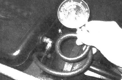
3.17. Using a simple vacuum gauge, you can make accurate diagnostics; before making a decision on the need for major repairs, it is imperative to carry out this test
18. Before measuring the vacuum level, pre-warm up the engine. Chock the wheels and apply the parking brake. With the gearshift lever in the "PARK" position, start the engine and let it idle.
Warning: Do not allow your hands or vacuum gauge to enter the fan blades.
19. Take vacuum gauge readings; a normal, well-functioning engine should create a steady vacuum of approximately 432 - 559 mm Hg (see illustration). The measurement results below indicate the following engine conditions.

3.19. Typical vacuum gauge parameters
- a) A persistently low vacuum reading usually indicates a leak in the intake manifold/throttle body gasket, a faulty vacuum hose, extremely late ignition timing, or incorrect valve timing. Check the ignition timing angle setting using a stroboscope, and eliminate other possible causes by performing the checks described in this chapter before removing the timing chain cover to check the position of the valve timing marks.
- b) If the vacuum gauge readings are unstable and 80-200 mm below the required value, it should be assumed that the intake manifold gasket on the intake channel is leaking or the fuel injector is faulty.
- c) If the stable vacuum gauge readings are below the given value by approximately 50-100 mm, it should be assumed that the valves are not tight in the closed position. Perform a compression test and leak test to confirm your suspicion.
- d) An unstable or sudden drop in pressure may be due to a stuck valve or misfiring. Perform a compression test, check for leaks, and inspect the spark plugs.
- e) Rapid fluctuations of the vacuum gauge needle with an amplitude of approximately 100 mm Hg at engine idle speed, combined with increased smoke emission from the exhaust pipe, indicate wear of the valve guide bushings. Perform a leak test to confirm your suspicion. If the needle begins to vibrate rapidly as the engine speed increases, check the tightness of the intake manifold or cylinder head gasket, and also make sure that. that the valve springs are not weakened, the valves are not burnt out, and the ignition system is working without failures.
- f) A slight fluctuation of the pointer with an amplitude of approximately 100 mm Hg most likely indicates a problem with the ignition system. Perform all relevant checks as for maintenance and, if necessary, perform an ignition function test using a special analyzer.
- g) If the vacuum gauge needle fluctuates with a significant amplitude, measure the compression in the cylinders and check for leaks to detect a failed engine cylinder or to ensure that the cylinder head gasket is leaking.
- h) If the needle fluctuates slowly over a wide range, check the crankcase ventilation (PCV) system for leaks, the idle air-fuel mixture ratio for leaks, and the throttle body and intake manifold gasket for leaks.
- j) Increase the crankshaft speed to 2500 rpm and release the gas pedal sharply. If the engine is in normal operating condition, the vacuum level should then tend to zero, then exceed the normal value by approximately 130 mm Hg and return to its normal position at engine idle. If the vacuum level increases slowly, without reaching its maximum value when the throttle valve is closed, the piston rings may be critically worn. If the arrow moves with a delay, then the exhaust system may be restricted (often the muffler or catalytic converter is clogged). A simple way to identify a blocked component is to disconnect the exhaust system upstream of the component being tested and re-test the vacuum level.