
2. To obtain accurate test results, the engine must be warmed up to normal temperature and the battery must be fully charged.
3. Remove the spark plugs. Open the throttle fully, turn off the ignition by disconnecting the low-voltage wires from the coil.
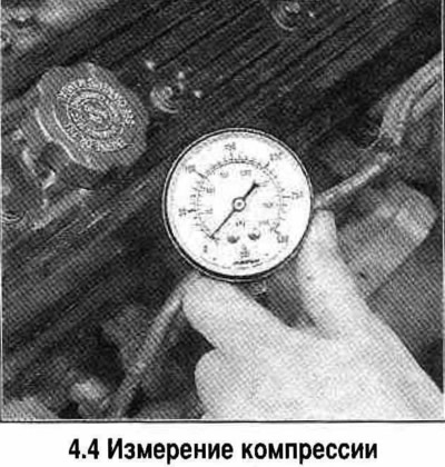
4. Insert the compression gauge into the spark plug hole of cylinder 1 (see photo). Turn on the starter and watch the pressure gauge. On a working engine, the pressure should build up quickly. Low pressure after the first stroke of the piston and a slow build-up during subsequent compression strokes indicates worn piston rings. If the pressure is low after the first stroke of the piston and does not build up during subsequent compression strokes, the cause is a leak in the valves or a leaky gasket or cylinder head. Record the highest compression reading.
5. Repeat the procedure for the remaining cylinders.
6. If after introducing oil into the cylinder the compression increases, then we can conclude that the piston rings are worn. If the compression increases slightly, then the leak occurs through the valves or the head gasket.
7. If the compression is equally low only in two adjacent cylinders, then the most likely cause is a burnt gasket between these cylinders.
8. If the compression value exceeds the norm, then the combustion chamber is covered with carbon deposits. In this case, the cylinder head must be removed and the carbon deposits removed.
9. If there is a significant difference in compression in the cylinders, the car should be taken to a service station to have the cylinder head and block checked for leaks using the pressure testing method.
Warning: Before starting the engine, carefully check the condition of the fan blades (the presence of damage or cracks on them). When the engine is running, do not place your hands too close to the fan, keep the appliance at a sufficient distance from the fan and do not stand in line with the rotating impeller.
Check the vacuum gauge reading. On a working engine, the vacuum gauge should show a vacuum of 430-560 mm Hg, and the instrument needle should be practically motionless.
Below is a description of the nature of the vacuum gauge readings and the method for determining the engine condition based on them.
a. Too low a vacuum level usually indicates a leak in the intake manifold-to-throttle body gasket, a leak in the vacuum hose, or too late ignition timing or incorrect valve timing. Before removing the timing belt covers and checking the alignment of the timing marks, check the ignition timing with a timing light and eliminate all other possible causes using the testing procedures described in this Chapter.
b. If the vacuum gauge readings are 75-200 mm Hg below normal and are unstable (the arrow twitches), then this indicates a leak in the gasket at the inlet of the intake manifold or a faulty injector.
c. If the pointer regularly deviates by 50-100 mm Hg, then the cause is leaky valves. To confirm this conclusion, check the compression in the engine cylinders.
g. The needle irregularly deflects toward low readings, or trembles and shows low vacuum. The probable cause is increased resistance to valve movement, or interruptions in the operation of the cylinders. Check the compression in the cylinders and inspect the spark plugs.
d. If the needle quickly fluctuates within 100 mm Hg at idle speed, and the engine operation is accompanied by smoke from the muffler, then the valve guides are worn out. To check this conclusion, it is necessary to conduct combustion chamber leak tests (with air pumping). If the pointer fluctuates rapidly and at the same time an increase in engine speed is observed, then it is necessary to check the tightness of the intake manifold gasket, the elasticity of the valve springs. Such readings can also be caused by burnt valves and interruptions in the operation of the cylinders (ignition failures).
e. Weak fluctuations of the arrow (within 20-30 mm Hg in both directions) indicate unstable ignition operation. Check all provided settings and adjustments, if necessary, connect an ignition system analyzer to the engine.
h. If the needle fluctuates greatly, check the compression in the cylinders or perform leak tests, as the cause of the malfunction may be a non-working cylinder or a leaky cylinder head gasket.
g. If the instrument readings change slowly over a wide range, then check the cleanliness of the forced crankcase ventilation system pipes, the correct adjustment of the combustible mixture, the tightness of the throttle body gaskets, or the intake manifold.
i. Open the throttle valve sharply, and when the engine speed reaches 2500 rpm, release the valve. The valve should slowly return to its original position. The vacuum gauge readings should drop to almost zero, then increase and exceed the control readings corresponding to steady-state idle speed by approximately 125 mm Hg, after which the vacuum should be restored to the previous level. If the vacuum is restored slowly, and when the valve is opened sharply, the control reading is not exceeded, then the cause may be wear of the piston rings. If the vacuum is restored extremely slowly, check the cleanliness of the exhaust tract (usually a muffler or catalytic converter). The simplest way to check this is to open the exhaust tract before the suspect section and repeat the test.
Checking the compression in the engine cylinders
a. The results of the compression test in the engine cylinders allow us to judge the condition of a group of parts in the upper part of the engine (pistons, rings, valves and cylinder head gaskets). Namely, a decrease in compression may be caused by leaks in the combustion chambers due to wear of the piston rings, damage to the valve heads and seats, or burnout of the cylinder head gasket.
Note: To obtain accurate test results, the engine must be warmed up to normal temperature and the battery must be fully charged.
b. Start by cleaning the areas around the spark plugs using compressed air (if you don't have a compressor, blow out the areas with a car or even a bicycle pump). This is necessary to prevent dirt from getting into the cylinders when measuring compression.
c. Remove the spark plugs.
g. Open the throttle valve fully and secure it in this position.
d. Disconnect the central high-voltage wire from the ignition distributor cap, connect it to ground on the cylinder block. For reliability, connect to ground using a special short-circuiting piece of wire with alligator-type clamps on both ends. It also does not hurt to remove the fuse of the electronic fuel injection system on the mounting block, which will ensure complete shutdown of the electric fuel pump when measuring compression.
d. Insert the compression gauge into the spark plug hole.
e. Turn on the starter and turn the crankshaft a few revolutions, monitoring the readings of the compression gauge. On a serviceable engine, the pressure should increase quickly. Low pressure after the first stroke of the piston and a slow increase during subsequent compression strokes indicates wear of the piston rings. If the pressure is low after the first stroke of the piston and does not increase during subsequent compression strokes, then the cause is a leak in the valves or a leaky cylinder head gasket (the cause may also be the formation of cracks in the head). Reduced compression can also be caused by carbon deposits on the valve heads. Record the highest compression reading.
z. Repeat the measurement procedure for the remaining cylinders, compare the results with the standard data.
g. Inject some engine oil into each cylinder through the spark plug hole (about three full syringe oilers), then repeat the tests.
and. If the compression increases after adding oil, then we can make a clear conclusion that the piston rings are worn out. If the compression increases slightly, then the leak is through the valves or the cylinder head gasket. Leakage through the valves can be caused by burnt-out valve seats and/or chamfers, as well as deformation of the valve stems or the formation of cracks on them.
k. If the compression is equally low only in two adjacent cylinders, then the most likely cause is a burnt gasket between these cylinders. Confirmation of this conclusion will be the appearance of traces of coolant in the combustion chambers or in the crankcase of the cylinder block.
l. If the compression value in one of the cylinders is 20 percent lower than in the other cylinders and the engine runs unsteadily at idle, then the cause may be wear of the camshaft cam that controls the exhaust valve.
m. If the compression value exceeds the norm, the combustion chamber is covered with carbon deposits. In this case, the cylinder head must be removed and the carbon removed.
n. If the compression in all cylinders is low, or varies greatly between cylinders, then it is necessary to conduct combustion chamber leak tests, for which you should contact a specialized workshop. As a result of the tests, leak locations should be accurately determined and a quantitative characteristic of the leak should be given.
Information taken from the official website «chevyman.ru»