
ChevyMan.ru
Mazda Mitsubishi Toyota Land Rover Honda Kia Nissan
English Русский
Български
Беларускі
Український
Српски
Hrvatski
Română
Polski
Slovenský
Magyar
|
Articles | Sitemap | Contacts |


Home   Aveo   Captiva   Cruze   Lacetti   Lanos   Niva   Tahoe   Others  
Orlando 1 (2010-2018) Trailblazer 1 (2001-2008, petrol) Lumina 1 (1989-1994)
  • Home
  • Chevrolet
  • Trailblazer 1
  • Transmission
  • Drive shafts and cardan
  • Cardan shaft(s) — removal and installation

Cardan shaft(s) — removal and installation (Chevrolet Trailblazer 1)

            0

Contents: Rear propeller shaft ↧ Front propeller shaft (all-wheel… ↧

Rear propeller shaft


Removal


1. Raise the vehicle with a jack and install supports. Place the gear selector in neutral and release the parking brake. Place chocks under the front wheels to prevent the vehicle from rolling.

2. Mark the original relative positions of the cardan shaft and the flange of the main gear shaft (see illustration). Subsequent installation of the shaft should be carried out in accordance with these marks to ensure that balance is maintained.
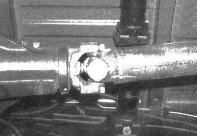
3.2. Mark the original relative positions of the rear propeller shaft and the differential pinion…

3.2. Mark the original relative positions of the rear propeller shaft and the differential pinion shaft


3. Remove the rear universal joint bolts and fastening strips. To access the bolts, you may have to turn the driveshaft or wheels slightly. To lock the driveshaft when loosening the bolts, insert a large screwdriver through the fork (see illustration).
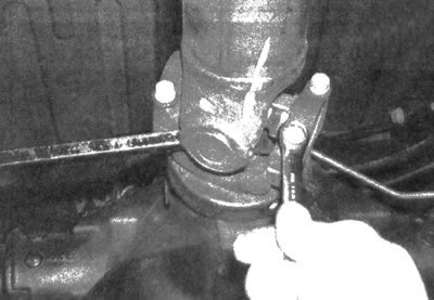
3.3 To lock the driveshaft when loosening the pinch bolts, insert a large screwdriver through the…

3.3 To lock the driveshaft when loosening the pinch bolts, insert a large screwdriver through the fork


4. To prevent the bearing caps from falling out during removal, tape them to the crosspiece with adhesive tape.

5. With the rear end of the propeller shaft lowered, disengage the splined fork at the front end from the gearbox or transfer case shaft, then remove the shaft.

6. Cover the hole of the extended part of the gearbox or transfer case housing with plastic film, then fix the film on the housing with a rubber ring. This will prevent fluid from leaking out and dirt from getting into the gearbox when the driveshaft is removed.

Installation


7. Remove the plastic film from the extended portion of the transmission or transfer case housing and thoroughly clean the surrounding area. Inspect the seal carefully. IN chapter 7 the procedure for replacing this seal is described.

8. Engage the splined fork installed at the front of the propeller shaft with the output shaft of the gearbox or transfer case.

9. Lift the rear end of the driveshaft and place it in its original position. Make sure that the previously applied marks for the relative positions of the elements are aligned. If necessary, rotate the rear wheels until the marks are aligned.

10. Remove the tape holding the bearing caps to the crosspiece and install the mounting strips and bolts. Tighten all mounting bolts to the torque specified in the specifications in this chapter.

Front propeller shaft (all-wheel drive models)


Removal


11. Raise the front of the vehicle with a jack and install vertical supports. Remove the protective plate if necessary.


12. Mark the original relative positions of the front propeller shaft and the front differential gear flange.

13. Unscrew the bolts and remove the mounting strips located on the differential flange.

14. Pull the driveshaft back enough to disengage it from the differential flange, then lower the shaft and pull it out of the transfer case.

Installation


15. Insert the rear end of the propeller shaft into the splined connection of the secondary shaft of the transfer case. The reliability of the connection made should be confirmed by a distinct click of the locking ring.

16. Connect the front end of the propeller shaft to the differential flange (align the initial relative position marks), install the fastening strips and bolts, then tighten the fasteners to the torque specified in specifications this chapter.

17. Install the protective plate if necessary.

The article was checked: Vladimir Romannikov
This article is available at russian, bulgarian, belarusian, ukrainian, serbian, croatian, romanian, polish, slovak, hungarian

Share information:

Previous articles
Trailblazer 1: Drive shafts and cardan
Next articles

Cardan shafts and joints — general information and inspection
General information
Transmission — Specifications
Cardan joints — replacement
Bridges — description and inspection
Half shafts (rear) — removal and installation
Axle shaft seal (rear) — replacement
Axle shaft bearing (rear) — replacement


See similar articles on the topic of Chevrolet cars:
Replacing the wheel drive shaft seal Chevrolet Aveo T250 (2006-2011)
Cardan shaft — removal and installation Chevrolet Captiva 1 (2006-2018)
Secondary shaft repair Chevrolet Cruze 1 (2008-2016)
Removal the intermediate steering shaft Chevrolet Lacetti 1 (2002-2009)
Removal and installation the cardan shaft Chevrolet Niva 1 (2002-2016)
Cardan shaft — removal and installation Chevrolet Tahoe 1 (1992-2000)
Link in different formats to this page


Visitor comments

No comments yet


How much will 11 + 10 =


Orlando 1 (2010-2018) 
  • General information
  • Introduction to manual
  • User manual
  • Maintenance
  • Troubleshooting
  • Power unit
  • Engine repair
  • Fuel and control system
  • Cooling and lubrication system
  • Ignition system
  • Transmission
  • Clutch
  • Gearbox
  • Drive shafts
  • Chassis
  • Car suspension
  • Steering
  • Brake system
  • Body
  • Exterior (external elements)
  • Doors, locks and windows
  • Electrical equipment
  • Equipment and devices
  • Windscreen wipers
  • Power devices
  • Electrical diagrams


Trailblazer 1 (2001-2008) 
  • General information
  • User manual
  • Troubleshooting
  • Maintenance
  • Power unit
  • Engine in a car
  • Engine overhaul
  • Cooling and heating
  • Fuel and exhaust system
  • Engine electrical equipment
  • Engine control
  • Transmission
  • Automatic gearbox
  • Transfer case
  • Drive shafts and cardan
  • Chassis
  • Brake system
  • Car suspension
  • Steering
  • Body
  • Exterior (external elements)
  • Interior (internal elements)
  • Doors, locks and windows
  • Electrical equipment
  • Equipment and devices
  • Electrical circuits


Lumina 1 (1989-1994) 
  • General information
  • Maintenance
  • Power unit
  • Engine 3.1L V6
  • Engine 3.8L V6
  • Engine overhaul
  • Cooling system
  • Power and exhaust system
  • Fuel injection
  • Engine electrical equipment
  • Reduced exhaust gas toxicity
  • Transmission
  • Automatic gearbox
  • Drive shafts
  • Chassis
  • Brake system
  • Car suspension
  • Steering
  • Body
  • Heating and air conditioning
  • Repair of body elements
  • Doors, covers and windows
  • Interior (internal elements)
  • Electrical equipment
  • Equipment and devices
  • Electrical circuits


ChevyMan.ru © 2017-2026 · Mobile version · Feedback · Site search · Interesting to read · Sitemap: EN BG BY UA RS HR RO PL SK HU

Aveo 2003-2008 · Aveo 2006-2011 · Aveo 2012-2018 · Captiva 2006-2018 · Cruze 2008-2016 · Lacetti 2002-2009 · Lanos 2002-2009 · Niva 2002-2016 · Tahoe 1992-2000 · Tahoe 2000-2014 · Lumina 1 1989-1994 · Trailblazer 1 2001-2008 · Orlando 1 2010-2018 ·
🛡️ For your security and to improve our service, this site uses cookies. You can disable them in your browser.