


Contents: Removal ↧ Installation ↧
Removal
1. Loosen the rear wheel mounting nuts. Raise the rear of the vehicle with a jack and install stands. Place chocks under the front wheels. Remove the wheel and brake disc (see chapter 9).
2. Remove the differential cover and drain the oil into a container placed in advance.
3. Remove the differential gear shaft clamp bolt (see illustration).
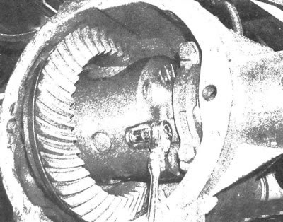
6.3. Remove the differential gear shaft clamp bolt
4. When performing the procedure on a vehicle with a conventional differential design (without lock function) the gear shaft should be removed. If the differential has a locking feature, extend the pinion shaft and rotate the differential until the shaft contacts the housing to create the clearance needed to remove the locking clips (see illustration).
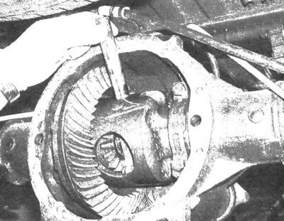
6.4 Pull out the pinion shaft to gain access to the locking brackets (do not turn the axle shafts after pulling out the shaft, as this will cause the crosspiece to shift from its original position)
5. Have an assistant press in the outer flange end of the drive shaft and remove the locking clip located in the groove of the inner end of the shaft (see illustration).
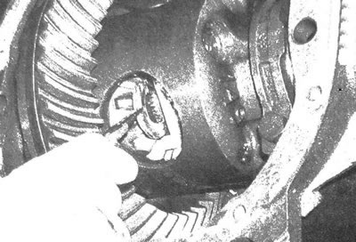
6.5a. Press in the axle flange, then remove the locking clip located on the inner end of the drive shaft
Note: If the differential has a locking function, use a screwdriver to turn the bracket so that the open part is facing inward (see illustration).
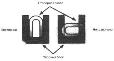
6.5b. On vehicles with a differential that has a locking function, before removing the bracket, it must be positioned as shown
6. After removing the bracket, remove the semi-axle without damaging the oil seal (it should be noted that whenever the semi-axle is removed, it is advisable to replace the oil seal without fail see subsection 7). Some models are equipped with a thrust washer in the differential. When removing the axle shaft, do not allow the washer to fall out.
Installation
7. Carefully insert the axle shaft into the housing and securely connect it to the differential.
8. Place the locking bracket into the groove of the drive shaft and pull out the flange to lock it in place.
9. Insert the gear shaft, align its hole with the hole of the clamp bolt and insert the bolt.
Note: Before installation, coat the bolt threads with a special anaerobic compound.
Tighten the clamp bolt to the specified torque.
10. Inspect the cover gasket. If the condition is satisfactory, installation of the existing gasket is permissible. If the gasket is damaged, replace it. Install the cover and tighten its bolts to the required torque, then fill the differential with oil of the type specified in chapter 1.
11. Install the brake disc, caliper bracket and caliper. Tighten the fasteners to the torque values given in chapter 9. Install the wheel and its nuts. Lower the vehicle and tighten the wheel nuts to the torque value given in specifications of chapter 1.