
Inspection
1. Loosen the wheel nuts, jack up the car and install supports. Remove the wheel and reinstall the wheel nuts to press the disc against the hub flange.
Note: If the disc does not make contact with the hub when the nuts are fully tightened, place washers underneath them.
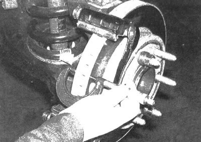
2. Remove the brake caliper. Do not disconnect the brake hose from it. After unscrewing the caliper mounting bolts, hang it on a piece of wire (see illustrations).
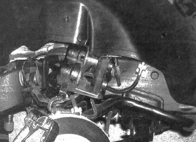
5.2. Hang the caliper on a piece of wire - do not allow the brake hose to be pulled
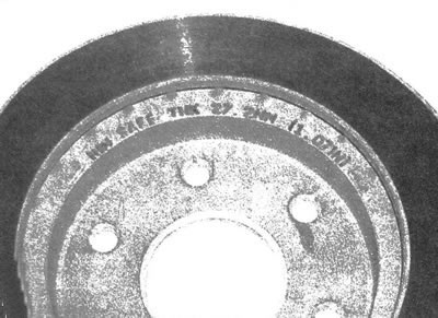
3. Inspect the disc surface for scratches and other signs of damage. The presence of small scratches and small chips on the surface of the disc in use is acceptable and does not reduce the reliability of the brakes. If there are deep scratches on the surface, the disc should be removed and mechanically processed in a car repair shop.
Be sure to inspect the disc from both sides (see illustration). If you feel a pulsation in the pedal when braking, determine the disc runout.
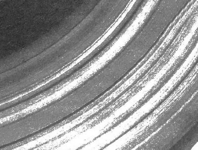
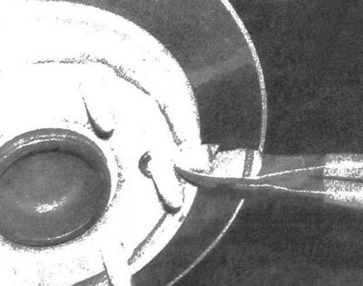
5.3. The vehicle on which this brake disc was installed was operated for a long time with extremely worn pads; as a result, the disc developed grooves of such depth that it cannot be restored
4. Using a dial gauge, check the disc runout by placing the gauge rod 13 mm from the outer edge (see illustration). Set the indicator arrow to zero and turn the disk. The indicator reading must not exceed the value specified in the specifications of this chapter. If the disc runout exceeds the norm, the surface should be mechanically treated.
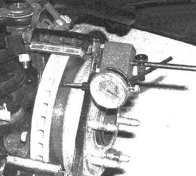
5.4a. Using a dial gauge, check the disc runout, secure the gauge and turn the disc
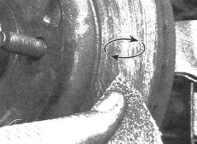
5.4b. Using circular motions, sand the surface of the disc with sandpaper
Note: The manufacturer's specialists recommend mechanical treatment of brake discs only if their uneven surface causes pulsation of the brake pedal, or if spots are found on the surface resulting from overheating. If you decide not to machine the discs, sand their surface using sandpaper (see illustration).
5. During mechanical processing, the thickness should not be brought to the limit, the value of which is cast on the back surface of the disc (see illustration). The thickness of the disc is measured using a micrometer (see illustration).
5.5a. Minimum permissible (critical) the thickness of the disc is cast on its surface
5.5b. Using a micrometer, measure the thickness of the disc at several points.
Removal
6. Unscrew the two mounting bolts and detach the caliper bracket (see illustrations).
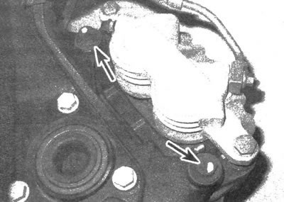
5.6a. Caliper bracket bolts (front)
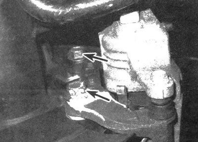
5.6b. Caliper bracket bolts (rear)
7. Unscrew the wheel nuts that held the disc in place and remove it from the hub. If the studs have pressed metal disc retainers, cut and remove them (see illustration). (When installing the disk, there is no need to install these clamps.)
5.7. If necessary, cut and remove the disc retaining washers (there is no need to install new fasteners during subsequent assembly)
Installation
8. Place the disc on the studs.
9. Install the caliper bracket and tighten the mounting bolts to the required torque. Install the brake pads.
10. Install the caliper onto the bracket and tighten the bolts to the required torque.
11. Install the wheel and secure it with nuts. Lower the vehicle onto a supporting surface. Tighten the wheel nuts to the torque value given in specifications of chapter 1. Press the brake pedal several times to bring the pads into contact with the disc. If the brake hose was not disconnected from the caliper, then there is no need to bleed the system. Before driving on the road, make sure that the braking system is working properly.