
Removal
1. Disconnect the negative battery cable.
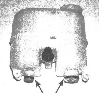
2. Disconnect the plug of the emergency fluid level indicator in the tank (see illustration).
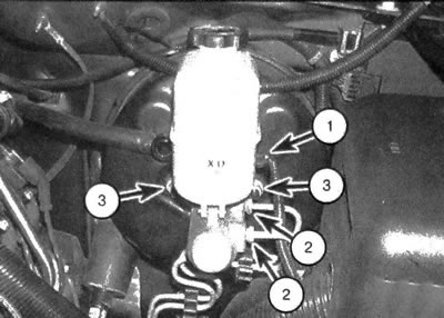
6.2. Brake Master Cylinder Parts A - Connector of the fluid level sensor in the tank; B - Connections of brake hydraulic system lines; C - Fastening nuts
3. Pump out as much brake fluid as possible from the master cylinder reservoir, using, for example, a culinary syringe.
Note: After such use, it is prohibited to use the culinary syringe for cooking.
4. Place absorbent cloths under the connectors and prepare suitable plugs or plastic bags to seal any exposed brake lines after disconnection.
Caution: Brake fluid can damage your vehicle's paintwork. Cover the painted surfaces of the vehicle to protect against brake fluid. During this procedure, try to avoid spilling liquid. Loosen the fittings that connect the brake lines to the master cylinder. To prevent the edges of the connecting nuts from rounding off, when unscrewing, use a spanner that fits around the hexagon of the fitting.
5. Pull the brake lines away from the master cylinder and plug the holes to prevent clogging of the system,
6. Unscrew the nuts securing the master cylinder to the brake booster (see illustration).
Pull the master cylinder off the studs and remove it from the engine compartment. Avoid spilling brake fluid.
Installation
7. Before installation, it is necessary to bleed the new master brake cylinder. Secure it in a vice by clamping the flange.
8. Connect two bleeder tubes to the master cylinder outlet fittings (see illustration).
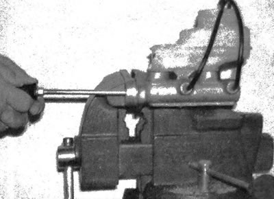
6.8. The most preferable method is preliminary bleeding of the master cylinder, when air is removed from it into the tank through two tubes
9. Fill the reservoir with the appropriate type of brake fluid (see chapter 1).
10. Slowly push the piston into the master cylinder to force air out of the chambers into the reservoir. To move the piston, you can use a large Phillips screwdriver. Since the tubes are immersed in the liquid in the tank, when the piston is released, no air enters the cylinder.
11. Continue pumping until no air bubbles are observed in the liquid.
12. Disconnect the bleed tubes (one at a time) and plug the cylinder fittings to prevent fluid from leaking out and air from entering. Install the tank lid.
13. Install the master cylinder onto the brake booster studs and tighten the nuts with your fingers. Don't forget to install a new gasket.
14. Connect the threaded couplings of the brake hydraulic system lines to the master cylinder. Since the cylinder nuts are not yet fully tightened, there should be no difficulty in guiding the union nut along the threads of the fitting. Avoid stripping the threads when tightening the nut.
15. Finally tighten the master cylinder mounting nuts and hydraulic system connectors. The nuts must be tightened to the required torque.
16. Fill the reservoir, then bleed the master cylinder and brake system circuits as described in subsection 8. To bleed the installed master cylinder, have an assistant press and hold the brake pedal in this position. Loosen the union nut. to release liquid containing air (see illustration). Tighten the nut, then have an assistant return the pedal to its original position. Continue bleeding through the two fittings until. until no air bubbles are observed in the liquid. Before you begin normal operation of your vehicle, make sure that its braking system is in good working order.
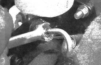
6.16. It is necessary to involve an assistant who will press and fix the brake pedal in this position. Loosen the union nut to release the air-containing fluid. Continue bleeding through the two fittings until no air bubbles are detected in the fluid
Warning: If the brake pedal does not become elastic after bleeding, or if there is any doubt about the serviceability of the brake system, it is PROHIBITED to drive the vehicle. It should be towed to a company station for diagnostics using special equipment.
Replacing the tank sealing ring
Note: If necessary, the reservoir can be replaced separately from the master cylinder body. To eliminate a leak that has occurred between the tank and the cylinder, you can replace the sealing ring located there.
17. Pump out as much brake fluid as possible from the master cylinder reservoir, using, for example, a culinary syringe.
Note: After such use, it is prohibited to use the culinary syringe for cooking.
18. Place a cloth under the master cylinder to absorb any fluid that spills when the reservoir is disconnected.
Caution: Brake fluid corrodes paintwork. Cover adjacent body parts and avoid spilling liquid during this procedure.
19. Using a hammer and a small punch, knock out the roller pins that secure the reservoir to the master cylinder (see illustration).
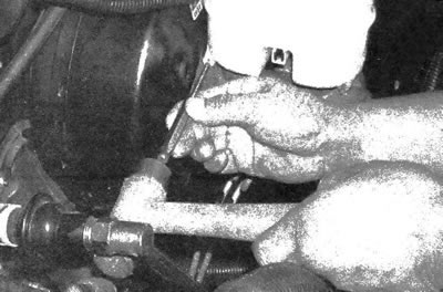
6.19. Knock out the roller pins that secure the reservoir to the master cylinder
20. Pull the reservoir off the master cylinder body.
21. If you are only replacing the O-rings, pry up and remove the old seals, then install the new rings in their place (see illustration).
6.21. If a brake fluid leak is detected, the reservoir sealing rings must be replaced
22. Lubricate the O-rings with clean brake fluid, then press the reservoir back into position on the master cylinder and secure it with new roller pins.
23. Fill the reservoir with the appropriate type of brake fluid (see chapter 1) and make sure there are no leaks.
24. Bleed the master cylinder (see illustration 6.16).