
Contents: Electro-hydraulic control unit (EHCU) ↧ Wheel sensors ↧ Emergency indicators ↧ Examination ↧
The anti-lock braking system is designed to maintain directional stability and controllability, as well as to ensure optimal deceleration of the vehicle during sudden braking on most types of road surfaces. This is achieved by monitoring the wheel speed and changing the fluid pressure in the corresponding system lines during braking, which prevents premature wheel locking.
The vehicles described use ABS with three sensors - one on each front wheel, and one sensor on each rear wheel. The rear wheel sensor on two-wheel drive vehicles is located in the extended portion of the gearbox housing, and on all-wheel drive vehicles, in the transfer case housing. Thus, the electronic unit of the system provides separate control of the front wheel brakes and general control of the rear brakes.
Electro-hydraulic control unit (EHCU)
The ABS modulator is located on the left frame side member. This element controls the pressure in the calipers, which prevents the wheels from locking during emergency braking (see illustration). This is ensured by the presence of a brake pressure monitoring valve (BPMV) and an electronic brake control unit (EBCM). When the EBCM registers wheel locking, (based on wheel sensor signals) the BPMV valve is triggered and the pressure in the corresponding support decreases. After the wheel speed has stabilized, the primary pressure is again created in its support. This cycle is repeated many times per second, resulting in pulsation in the brake pedal.
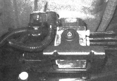
2.2 The ABS electro-hydraulic modulator (EHCU) is located longitudinally on the left frame member, under the driver
Note: The modulator can create pressure in the hydraulic system that exceeds the pressure. created by the brake cylinder. The possibility of turning on the brakes directly from the modulator has been eliminated.
In addition to receiving and processing data from wheel sensors and monitoring hydraulic pressure, the EBCM also monitors the system's condition and records diagnostic codes corresponding to specific faults that may occur in the braking system.
Wheel sensors
Each front wheel is equipped with a speed sensor. The sensors are located on the front hubs/bearings. The bearing has a toothed pulse wheel integrated into it. If the ring is damaged, the entire hub/bearing must be replaced. If the sensitive element of the sensor, which is bolted to the hub, fails, the element must be replaced separately. The sensors cannot be adjusted or disassembled.
The speed of the rear wheels is monitored by the VSS, which is located in the extended portion of the transmission housing on two-wheel drive vehicles and in the transfer case housing on four-wheel drive models. A more detailed description of the VSS sensor is provided in Chapter 6.
The wheel rotation speed in the sensor is determined by the revolutions of the toothed pulse wheel. When a gear tooth passes near the sensitive element, an alternating pulse is generated. The frequency of alternating pulses directly depends on the wheel speed. When impulses from sensors are received, the EVSM monitors changes in wheel speed. When a wheel lock is detected with EBCM, the ABS system is activated.
Emergency indicators
ABS has a self-diagnosis function. Every time the engine is started, the EVSM performs a system diagnostic. There are two brake system warning lights on the instrument panel: a red "Brake" light and an amber "ABS" light. Each light has specific functions. The "Brake" indicator lights up when a general problem occurs in the brake system, such as a drop in the brake fluid level. This indicator also comes on when the parking brake is applied. If the indicator does not turn off after the parking brake is released, it is necessary to check the brake fluid level in the master cylinder reservoir (see chapter 1).
The amber "ABS" indicator comes on when there is a problem with the anti-lock braking system that does not apply to the entire braking system. When the indicator lights up, it indicates that the ABS function has been lost, but the braking system remains operational in normal mode. In this case, diagnostics and repairs are carried out at the company's station.
Examination
Diagnostics should be carried out at a service and repair station using special equipment, but a car mechanic can carry out a number of simple checks before sending the car to the station.
- a) Inspect the relevant fuses.
- b) Make sure that the electrical connectors of the control unit and the ABS hydraulic regulator are securely connected.
- c) Make sure that the wires are intact and that the connectors of the wheel sensors and brake light sensor are securely connected.
- d) Inspect hydraulic lines, calipers and wheel cylinders.
If the above checks do not reveal the cause of the malfunction, the vehicle should be sent to a service and repair station for diagnostics using special equipment. Due to the complexity of this system, repair work should be entrusted to highly qualified specialists.