


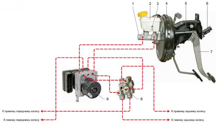
Elements of the car braking system: 1 - master brake cylinder; 2 — hydraulic reservoir; 3 - brake fluid level sensor; 4 - vacuum booster; 5 — pedal assembly bracket; 6 - brake light switch; 7— brake pedal; 8 — splitter, 9 — ABS unit.
The service brake system is hydraulic, dual-circuit, with diagonally separated circuits. In normal mode, when the system is in good working order, both circuits operate. In case of failure (depressurization) one of the circuits, the other circuit ensures the braking of the car, although with less efficiency. The working brake system includes the wheel brake mechanisms, pedal assembly, vacuum booster, master brake cylinder, hydraulic drive reservoir, anti-lock system unit, as well as connecting tubes and hoses.
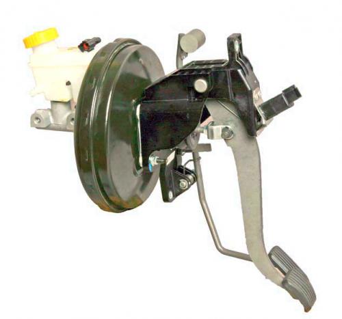
The brake pedal is of the suspended type. The brake light switch is installed in the pedal assembly bracket - its contacts close when the brake pedal is pressed.
The brake booster is located between the brake pedal and the master cylinder and is attached to the pedal assembly bracket with four nuts. The brake booster is non-disassemblable and is replaced with a new one when it fails.
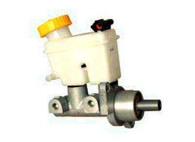
Master brake cylinder
The main brake cylinder is attached to the vacuum booster housing with two nuts. A common reservoir for the brake and clutch hydraulic drive is mounted on top of the cylinder, containing a reserve of fluid. The reservoir housing is marked with maximum and minimum fluid levels. A fluid level sensor is installed in the reservoir, which turns on the indicator in the instrument cluster when the fluid level drops below the MIN mark. When the brake pedal is pressed, the pistons of the main cylinder move, creating pressure in the hydraulic drive, which is supplied through pipes and hoses to the working cylinders of the wheel brake mechanisms.
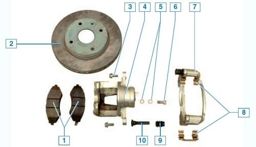
Elements of the front wheel brake mechanism: 1 - brake pads; 2 — brake disc; 3 — caliper mounting bolt to guide pin; 4 — support; 5 - copper sealing washers; 6 — brake hose mounting bolt; 7 — shoe guide; 8 - spring clamps; 9 — guide pin cover; 10 - guide pin
The front wheel brake mechanism is a disc type with a floating caliper, which includes a single-piston wheel cylinder.
For more efficient cooling, the brake disc is ventilated.
The brake shoe guide is attached to the steering knuckle, and the caliper is attached with two bolts to the guide pins installed in the holes of the shoe guide. Protective rubber covers are installed on the pins. Plastic grease is placed in the holes for the pins of the shoe guide.
When braking, the fluid pressure in the hydraulic drive of the brake mechanism increases and the piston, moving out of the wheel cylinder, made as a single unit with the caliper, presses the inner brake pad against the brake disc.
Then the support (by moving the guide pins in the holes of the guide pads) shifts relative to the disk, pressing the outer brake shoe against it. A piston with a sealing rubber ring is installed in the cylinder body. Due to the elasticity of this ring, a constant optimal gap is maintained between the disk and the brake shoes.
The rear wheel brake mechanism is a disc type with a floating caliper, which includes a single-piston working cylinder.
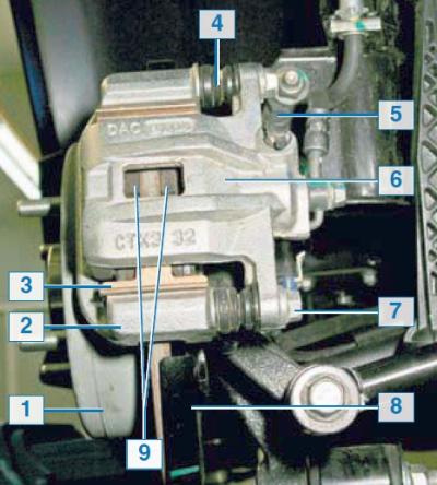
Rear wheel brake mechanism: 1 — brake disc; 2 - shoe guide; 3 - spring clip; 4 — guide pin cover; 5 — brake hydraulic system bleed nipple; 6 — support; 7 — caliper mounting bolt to guide pin; 8 — brake mechanism shield; 9 - brake pads
The design and operating principle of the rear wheel brake mechanism is similar to the front wheel brake mechanism.
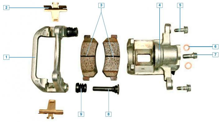
Elements of the rear wheel brake mechanism: 1 - shoe guide; 2 - spring clamp; 3 - brake pads; 4 — support; 5 — bolt for fastening the caliper to the guide pin; 6 - copper sealing washer; 7 — brake hose mounting bolt; 8 - guide pin; 9 — guide pin cover
The shoe guide is attached to the rear suspension knuckle.
The brake disc, unlike the front wheel brake disc, is not ventilated.
The parking brake mechanism is located in the central part of the brake disc. The parking brake mechanism is drum-type, with two brake shoes. Its design resembles a conventional drum brake mechanism.
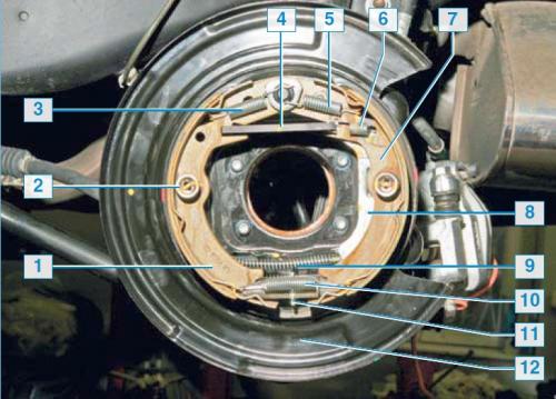
Parking brake mechanism: 1 - front shoe; 2 - spring cup; 3 - front shoe tension spring; 4 - spacer bar; 5 — rear shoe tension spring; 6 — pressure spring of the spacer bar; 7 - rear shoe; 8 — parking brake lever; 9 — parking brake cable; 10 - lower tension spring; 11 — clearance adjuster; 12 — brake mechanism shield
The brake drum for it is the inner side of the central part of the brake disc.
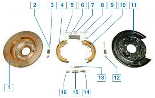
Elements of the parking brake mechanism: 1 — brake disc; 2 - support stand; 3 — brake shoe pressure spring; 4 - front shoe; 5 — front shoe tension spring; 6 - spacer bar; 7 - fixing plate; 8 — rear shoe tension spring; 9 — pressure spring of the spacer bar; 10 — rear shoe; 11 — brake mechanism shield; 12 — spring cup; 13 - lower tension spring; 14 — threaded regulator tip; 15 — regulator nut; 16 — regulator tip
All the parts of the parking brake mechanism are fixed on the brake mechanism shield. The parking brake drive lever is installed on the rear shoe, to which the parking brake cable is hooked. The upper ends of the shoes are pressed by tension springs to the spacer bar, and the lower ends are pressed to the gap adjuster between the shoes and the inner surface of the disk. The adjuster is a spacer bar consisting of two tips and a nut. One tip is threaded. When the nut is rotated, the length of the adjuster changes due to the threaded tip, as a result of which the adjuster moves the shoes apart or together.
The parking brake system drive is manual, mechanical, cable-operated, on the rear wheels. It consists of a lever with a rod and an adjusting nut, an equalizer, two cables and parking brake mechanisms in the brake mechanisms of the rear wheels.
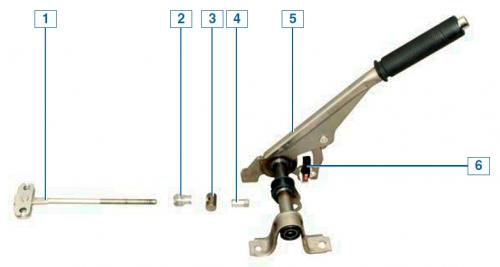
Parking brake lever: 1 - traction with cable equalizer; 2 - Nut lock; 3 - traction finger; 4 - adjusting nut; 5— parking brake lever; 6 — Parking brake and brake system malfunction indicator switch
The parking brake lever, mounted between the front seats on the floor tunnel, is connected to two cables via a rod and equalizer. The rear ends of the cables are connected to the parking brake actuator levers mounted on the rear shoes.
The parking brake is adjusted by turning the adjusting nut located on the rod with the cable equalizer.
All vehicles are equipped with anti-lock braking system (ABS).
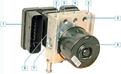
ABS block: 1 — control unit; 2 - hole for connecting the main brake cylinder tube; 3 - hole for connecting the brake tube of the left front wheel; 4 - hole for connecting the brake tube of the right front wheel; 5 - hole for connecting the brake tube of the left rear wheel; 6 — pump; 7 — hole for connecting the brake tube of the right rear wheel; 8 — hydraulic block;
Brake fluid from the master brake cylinder goes to the ABS unit, and from there to the brake mechanisms of all wheels. The ABS unit, fixed in the engine compartment on the left side member, near the front shield, consists of a hydraulic unit, a modulator, a pump and a control unit. ABS operates depending on the signals from the wheel speed sensors. The sensors are of the inductive type.
The front wheel speed sensor is installed in the hole of the steering knuckle and secured with a screw.
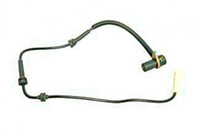
Front wheel speed sensor
The sensor's timing disk is pressed onto the outer drive joint housing.
The rear wheel speed sensor is built into the rear wheel hub.
If the rear wheel speed sensor fails, the hub must be replaced together with the sensor. When the vehicle is braking, the ABS control unit detects the start of wheel locking and opens the corresponding modulator valve to release the working fluid pressure in the channel. The valve opens and closes several times
per second, so you can verify that the ABS is working by the slight tremor of the brake pedal when braking. The ABS has a built-in brake force distribution (EBD) system, which acts as a pressure regulator in the hydraulic drive of the rear wheel brake mechanisms. If the rear wheels begin to lock when braking, the inlet valves of the rear wheel brake mechanisms in the modulator switch to the constant pressure maintenance mode, preventing further pressure increase in the working cylinders of the rear brake mechanisms. If the ABS malfunctions, the braking system remains operational, but the wheels may lock. In this case, a fault code is written into the unit's memory, which is read using special equipment at a service center. The traction control system (TCS), which uses signals from wheel speed sensors, is combined with the ABS.
The anti-lock braking system is controlled by the ABS control unit.
(The article was reprinted from the website «CHEVYMAN.ru»)