


In normal mode, when the system is in good working order, both circuits operate.
In case of refusal (depressurization) one of the circuits, the other circuit provides braking of the car, although with less efficiency.
The service brake system includes the wheel brake mechanisms, pedal assembly, vacuum booster, master brake cylinder, hydraulic drive reservoir, pressure regulators in the rear wheel brake mechanisms, as well as connecting tubes and hoses.
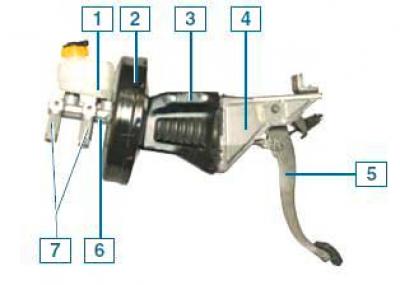
Pedal assembly with vacuum booster and master brake cylinder: 1 — hydraulic reservoir; 2 - vacuum booster; 3 — vacuum booster bracket; 4 — brake pedal bracket; 5 — brake pedal; 6 - master brake cylinder; 7— pressure regulators
The brake pedal is of the suspended type.
A brake light switch is installed in the pedal bracket; its contacts close when the brake pedal is pressed.
The brake booster is located between the brake pedal and the master cylinder and is secured with three nuts to the body and brake pedal brackets.
The vacuum booster is non-disassemblable; if it fails, it is replaced with a new one.
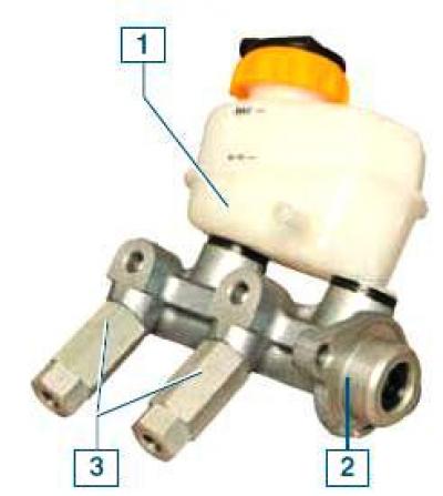
Master Brake Cylinder: 1 — reservoir for hydraulic drive of brake system and clutch; 2 - master brake cylinder; 3 - pressure regulators
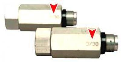
Marking of pressure regulators
The master brake cylinder is attached to the vacuum booster housing with two studs.
A common reservoir for the hydraulic drives of the brake system and clutch is installed on top of the cylinder, which contains a supply of fluid.
The tank body has marks for the maximum and minimum fluid levels, and a fluid level sensor is installed in the tank cap, which turns on the indicator in the instrument cluster when the fluid level drops below the MIN mark.
When the brake pedal is pressed, the pistons of the master cylinder move, creating pressure in the hydraulic drive, which is supplied through tubes and hoses to the working cylinders of the wheel brake mechanisms.
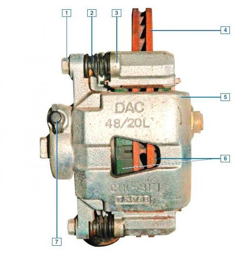
Front wheel brake assembly: 1 - caliper mounting bolt to guide pin; 2 - guide pin cover; 3 - shoe guide; 4 — brake disc; 5 — support; 6 - brake pads; 7 — brake hydraulic system bleed nipple
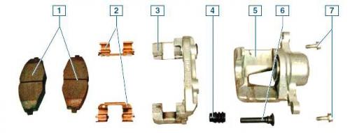
Elements of the front wheel brake mechanism: 1 - brake pads; 2 - spring clamps; 3 - shoe guide; 4 — guide pin cover; 5 — support; 6 - guide pin; 7 — caliper mounting bolt to guide pin
The front wheel brake mechanism is a disc type with a floating caliper, which includes a single-piston wheel cylinder.
The brake shoe guide is attached to the steering knuckle, and the caliper is secured with two bolts to the guide pins installed in the holes in the shoe guide.
The fingers are equipped with protective rubber covers.
Plastic grease is placed into the holes for the guide pins of the pads.
When braking, the fluid pressure in the hydraulic drive of the brake mechanism increases, and the piston, moving out of the wheel cylinder, made integral with the caliper, presses the inner brake pad against the disc.
Then the support (by moving the guide pins in the holes of the guide pads) shifts relative to the disc, pressing the outer brake pad against it.
A piston with a rubber sealing ring is installed in the cylinder body.
Due to the elasticity of this ring, a constant optimal gap is maintained between the disc and the brake pads.
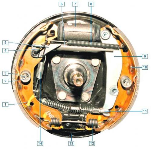
Rear wheel brake mechanism: 1 - front brake shoe; 2 - spring cup; 3 - support stand; 4 - earring; 5 — regulator lever; 6 - spacer bar; 7 - wheel cylinder; 8 - upper tension spring; 9 — parking brake lever; 10 - rear brake shoe; 11 — parking brake cable tip; 12 - lower tension spring; 13 - brake shield; 14 — regulator spring
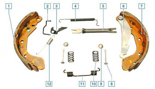
Elements of the rear wheel brake mechanism: 1 - front shoe; 2 - earring; 3 — regulator lever; 4 - upper tension spring; 5 - spacer bar; 6 — parking brake lever; 7 - rear shoe; 8 — support stand; 9 — spring cup; 10 - pressure spring; 11 - lower tension spring; 12 — regulator spring
The rear wheel brake mechanism is a drum type, with a two-piston wheel cylinder, two brake shoes and a device for automatic adjustment of the gap between the shoes and the drum.
The automatic clearance adjustment mechanism consists of a composite spacer bar of the shoes, an adjuster lever, a spring and an earring.
The automatic adjustment mechanism starts working when the gap between the pads and the brake drum increases.
When the brake pedal is pressed, the pistons of the wheel cylinder cause the shoes to move apart and press against the drum, while the projection of the regulator lever moves along the cavity between the teeth of the ratchet nut and constantly presses the tooth of the ratchet nut.
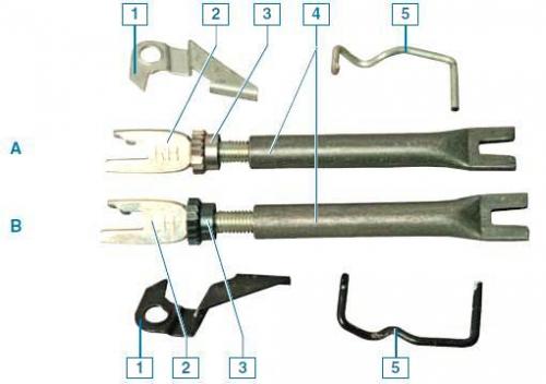
Elements of the mechanism for automatic adjustment of gaps between the pads and drums of the left and right rear wheels: A — brake mechanism of the right wheel; B — brake mechanism of the left wheel; 1 — regulator lever; 2 - threaded end of the spacer bar; 3 - ratchet nut; 4 - spacer bar; 5 - earring
When the brake pads are worn to a certain degree and the brake pedal is pressed, the adjuster lever has enough travel to turn the ratchet nut by one tooth, thereby increasing the length of the spacer bar and simultaneously reducing the gap between the pads and the drum.
This gradual lengthening of the spacer bar automatically maintains the gap between the brake drum and the shoes.
The wheel cylinders of the rear wheel brake mechanisms are identical.
The front brake pads of the rear wheels are the same, but the rear ones are different - they have mirror-symmetrical non-removable parking brake levers installed on them.
The left wheel brake adjuster lever, ratchet nut and clevis are black (the ratchet nut and the end of the spacer bar have a right-hand thread), and the right wheel is silver in color (the ratchet nut and the end of the spacer bar have left-hand threads).
The threaded end of the spacer bar on the right wheel is marked RH, and on the left wheel it is marked LH.
The brake adjuster levers for the left and right wheels are mirror-symmetrical.
To maintain the stability and control of the vehicle during braking, the brake drive uses fluid pressure regulators in the brake mechanisms of the rear wheels.
The working fluid is supplied to the rear wheel brake mechanisms through pressure regulators installed on the main brake cylinder.
When a certain fluid pressure in the main brake cylinder is reached, the regulators limit the increase in pressure in the wheel cylinders of the rear wheel brake mechanisms.
Both regulators must have the same markings.
The parking brake system is manual, mechanical, cable-operated, and operates on the rear wheels.
It consists of a lever with a front cable and an adjusting nut, an equalizer, two cables, drive levers in the brake mechanisms of the rear wheels and spacer bars.
The parking brake lever, mounted between the front seats on the floor tunnel, is connected to two cables via the front cable and equalizer.
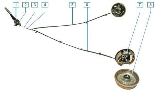
Parking brake system: 1 - parking brake lever; 2 - adjusting nut; 3 - front cable; 4 - equalizer; 5— right cable; 6 - left cable; 7 - left wheel brake mechanism; 8 - brake drum
The original article is on the website: «CHEVYMAN.ru»