


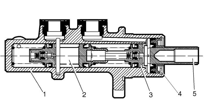
Figure 6-9. Master cylinder:
1 - cylinder body;
2, 3 - pistons of brake circuit drive;
4 - spacer washer;
5 - pusher.
Removal and installation. Disconnect the lines from the master cylinder and the connector with wires from the terminals of the brake fluid emergency level sensor. Close the openings at the lines and at the master cylinder to prevent fluid leakage from the system and the ingress of dust, dirt or foreign matter.
Remove the cylinder assembly with the reservoir by unscrewing the nuts that secure it to the vacuum booster. Remove the brake fluid emergency level sensor and drain the brake fluid from the reservoir and the cylinder. It is not recommended to remove the reservoir from the master cylinder unless necessary.
Install the master cylinder in the reverse order of removal. After installing the cylinder, bleed the hydraulic drive system to remove air from it.
Disassembly and assembly. The master cylinder is non-disassemblable and cannot be repaired. If it fails, it must be replaced.
Checking the tightness of the master cylinder. Install the master cylinder on the stand and connect it to the stand components as shown in Figure 6-10.
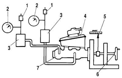
Figure 6-10. Master cylinder leak test diagram:
1 - valve for bleeding the stand;
2 - pressure gauge;
3 - absorption cylinder;
4 - master cylinder reservoir;
5 - pushrod offset indicator;
6 - flywheel;
7 - master cylinder.
Open valves 1 to bleed the stand and, moving the master cylinder pistons several times to the full length of their stroke, bleed the system. Then close valves 1. Rotating flywheel 5, slowly move the master cylinder pistons until the pressure monitored by pressure gauges 2 reaches 12.5 MPa (125 kgf/cm²). In this position, lock the master cylinder pushrod. The specified pressure should remain constant for at least 5 sec.
In case of fluid leakage or decrease in the set pressure within 5 seconds, replace the cylinder piston seals.
(The original article is on the website CHEVYMAN.ru)