


Caution! This operation should not be performed on vehicles equipped with ABS, as special equipment is required to properly bleed such brakes. Take the vehicle to a service shop or other repair shop that has the necessary tools.
Removal
1. Disconnect the cable from the negative terminal of the battery.
2. Disconnect the connector from the brake fluid level sensor (see illustration).
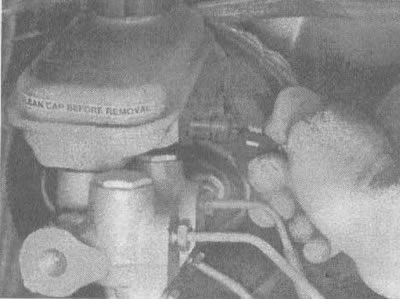
7.2. Disconnect the brake fluid level sensor connector
3. Place rags under the pipe connections and prepare caps or plastic plugs to plug the ends of the pipes after they are disconnected.
Caution! Brake fluid can damage paintwork. While working, cover all painted parts and proceed with caution to avoid spilling brake fluid.
4. Loosen the tightening of the pipes (couplings) at the ends of the brake fluid lines where they enter the master brake cylinder (see illustration). To avoid stripping edges, use a socket wrench that covers the hexagon.
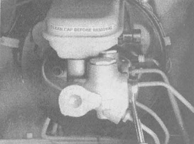
7.4 Disconnect the brake fluid lines using a socket wrench
5. Pull the brake lines away from the master cylinder and plug their outlets to prevent contamination.
6. Loosen the two nuts and remove the master cylinder from the vehicle.
7. Remove the tank cap and its diaphragm, then drain all remaining liquid.
Repair
8. Clamp the master cylinder in a vice. Be sure to place rags or wooden blocks between the jaws of the vice to avoid damaging the brake cylinder body.
9. Remove the pins (see illustration) with a 1/8-inch punch. Pull them up and separate them from the brake master cylinder housing. Remove the two sealing rings.
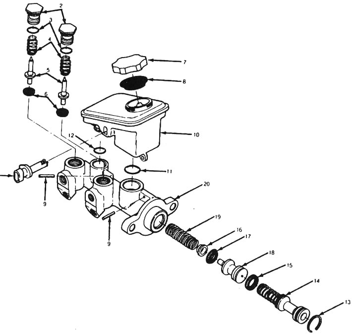
7.9. Details of the master brake cylinder: 1 - brake fluid level sensor, 2 - pressure limiting valve plugs, 3 - sealing ring, 4 - spring, 5 - valve piston, 6 - valve cuff, 7 - reservoir plug, 8 - diaphragm, 9 - pin, 10 - reservoir, 11 - sealing ring, 12 - sealing ring, 13 - retaining ring, 14 - primary piston, 15 - cuff, 16 - spring plate, 17 - cuff, 18 secondary piston, 19 - spring, 20 - brake master cylinder housing
10. Remove the pressure relief valve plugs (see illustration 7.9). Remove the O-rings, springs, pistons and valve seals. Be careful not to scratch or otherwise damage the rods or holes. Set each valve aside separately.
11. Remove the primary piston retaining ring by pressing on the piston and prying the ring with a screwdriver (see illustration).
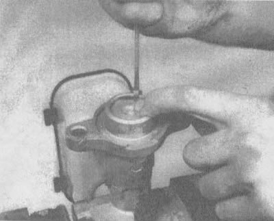
7.11 Press the piston down and remove the primary piston retaining ring
12. Remove the primary piston (see illustration).
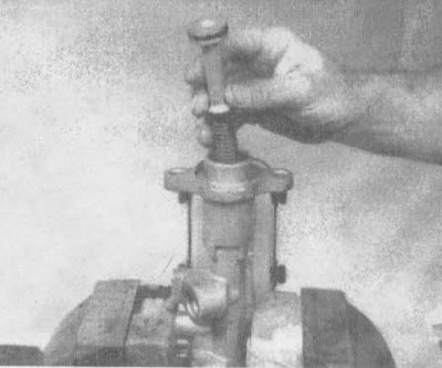
7.12 Remove the primary piston
13. Remove the secondary piston. It may be necessary to remove the master cylinder and gently tap it with a block of wood to expose the piston.
14. Clean the master cylinder body, primary and secondary pistons, pressure limiter valves and reservoir with brake cleaner or denatured alcohol and dry them with compressed air.
Warning! Do not use petroleum-based solvents to clean brake parts under any circumstances (gasoline, kerosene, etc)!
15. Check the master cylinder piston bore for any signs of corrosion, scratches or grooves. If there is any noticeable corrosion or damage, replace the master cylinder housing - do not attempt to use abrasive materials in an attempt to clean the bore.
16. Remove the old seal from the secondary piston and install a new one so that its edges are facing outward (see illustration).
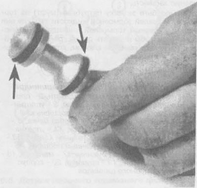
7.16. The secondary piston seals should be installed so that their edges are directed as shown in the photo
17. Install the spring plate to the secondary piston.
18. Lubricate the cylinder with clean brake fluid and install the spring and secondary piston (see illustration).
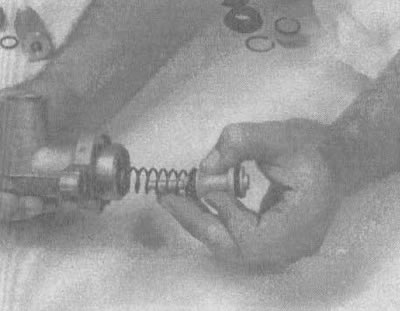
7.18. Insert the secondary piston
19. Disassemble the primary piston, paying attention to the location of the parts, then lubricate the seals with clean brake fluid and install them on the piston (see illustration).

7.19a. The primary piston seal must be installed so that the edges are directed away from the piston |
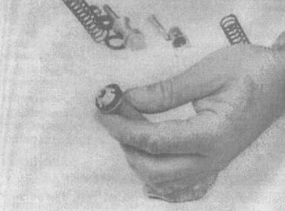
7.19b. Install a seal guard over the seal |
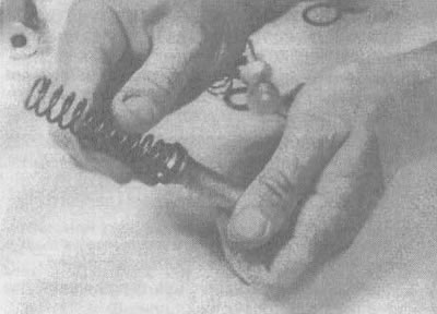
7.19v. Put the primary piston spring in place |
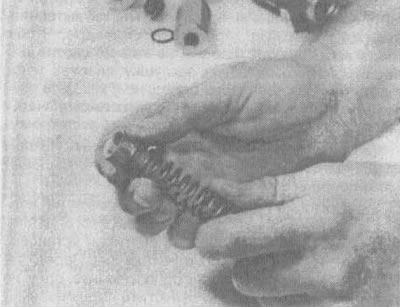
7.19g. Place the spring plate on the spring |
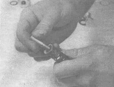
7.19d. Insert the spring mounting bolt through the plate and spring and screw it into the piston |
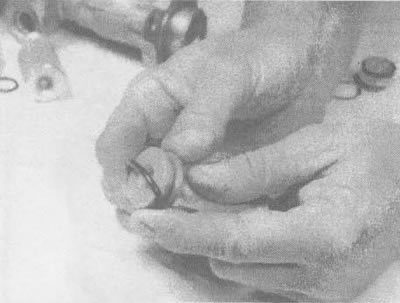
7.19e. Lubricate the sealing ring with clean brake fluid, then place it on the piston |
20. Insert the primary piston into the cylinder (see illustration), press it down and install the snap ring.
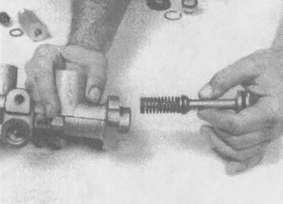
7.20. Insert the primary piston into the cylinder
21. Check the pressure limiting valves for signs of corrosion, scratches and grooves. Replace valves if necessary.
22. Lubricate the new O-rings and valve seals with the silicone grease included in the repair kit. Also lubricate the valve piston rods.
23. Place new seals on the pressure limiting valve pistons so that the edges of the seals are directed towards the plug.
24. Insert the distribution valve pistons and seals into the master cylinder body.
25. Install the springs into the master cylinder housing.
26. Install new sealing rings into the corresponding grooves in the valve plugs.
27. Insert the pressure limiting valve plugs into the brake master cylinder and tighten them to the torque specified in the specifications of this chapter.
28. Check the tank for cracks or signs of deformation. If any damage is noticed, replace the tank.
29. Lubricate the new reservoir sealing rings with clean brake fluid and insert them into the corresponding grooves in the master cylinder housing. Make sure they fit into the grooves.
30. Lubricate the reservoir hoses with clean brake fluid and install the reservoir on the body of the master brake cylinder, pressing it from top to bottom.
31. Insert new reservoir retaining pins. Be careful not to damage the reservoir or master cylinder housing.
32. Check the tank diaphragm and plug for cracks and deformation. Replace any damaged parts with new ones and attach the diaphragm to the cover (see illustration).
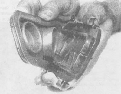
7.32. Install the diaphragm into the plug
Note: Always bleed the hydraulic system thoroughly when removing the master cylinder. You can reduce the time it takes to bleed the system by filling the master cylinder with brake fluid and bleeding it on a work bench (see pp. 33-36) before installing it on the vehicle.
33. Insert plugs with the correct thread size into the outlet holes of the brake lines and fill the reservoirs with brake fluid. It is necessary to support the brake cylinder so that the brake fluid does not spill during the bleeding procedure on the workbench.
34. Loosen one plug at a time and push the piston assembly into the bore to force air out of the master cylinder. To prevent air from being drawn back into the cylinder, the appropriate plug should be replaced before allowing the piston to return to its original position.
35. Make 3-4 strokes of the piston on each outlet port to ensure that all air trapped in the cylinder is removed.
36. Since the bench bleeding procedure does not involve the use of high pressure, an alternative is to remove and install plugs on each piston pass. Before pushing the piston in, remove one of the plugs completely. Before releasing the piston, instead of replacing the plug, place your finger firmly over the hole to prevent air from getting back into the master cylinder. Wait a few seconds for the brake fluid to be drawn from the reservoir into the piston barrel, then repeat the procedure. When you press the plunger, it will push your finger out of the hole, allowing air to escape. When only brake fluid comes out of the hole, put the plug back in place and continue bleeding on the other hole.
37. Fill the master cylinder reservoirs with brake fluid and install the diaphragm and plug. Note: To prevent overflow, when installing the lid, the tanks should only be filled to the top of the tank divider.
Installation
38. Carefully install the brake master cylinder, performing the disassembly procedure in reverse order, fill the reservoir with the recommended type of brake fluid (see chapter 1, section 4), then bleed the brakes at the master cylinder and at each wheel (see section 9).