


Caution! Brake pads should be replaced on both rear wheels at the same time - never replace the pads on just one wheel! Also, remember that dust generated in the brake system may contain asbestos, which is hazardous to health. Never blow it out with compressed air or inhale it. When servicing the brake system, it is necessary to wear a protective filter mask. Do not use petroleum based solvents to clean brake parts under any circumstances (kerosene and gasoline). Use only brake cleaner or denatured alcohol.
Attention! Each time the brake pads are replaced, the tension and retaining springs must be replaced. Because these springs are constantly subjected to heating and cooling cycles, they lose their elasticity over time and can allow the pads to become attached to the drums, causing the pads to wear significantly beyond normal levels. When replacing rear brake pads, use only high-quality original spare parts.
1. Loosen the wheel nuts, raise the vehicle and securely support it on struts.
2. Set the car to the parking brake.
3. Remove the wheel.
Note: All four rear brake pads must be replaced at the same time, but to avoid mixing up the parts, work on each brake assembly in turn.
4. Check the condition of the pads and replace if necessary (see illustrations 5.4a-5.4e). Note: If the brake drum cannot be pulled off the axle shaft, make sure the parking brake is fully released, then pour (squirt) a small amount of penetrating agent through the center of the hub. Let the product soak in and try to pull the drum off again. If the drum still does not tighten, you will have to remove the brake shoes. To do this, first remove the protrusion on the brake drum using a chisel and a hammer (see illustration 5.4a). Once the tab is removed, pull the lever off the wheel adjuster screw with a small screwdriver while turning the adjuster wheel with another small screwdriver and moving the shoes away from the drum. Now the drum can be pulled off. The drum needs to be replaced.
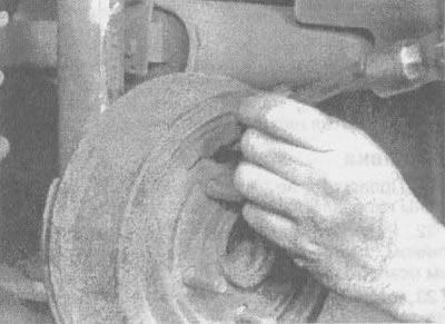
5.4a. If the brake drum cannot be removed, it may be necessary to remove the protruding outline using a chisel and hammer (on some vehicles, it has to be drilled with a 7/16-inch drill bit), then turn the adjusting screw to move the brake shoes away from the drum |
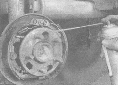
5.4b. Before removing anything, clean the brakes with brake cleaner or denatured alcohol; do not use compressed air to blow dust out of the brake assembly! |
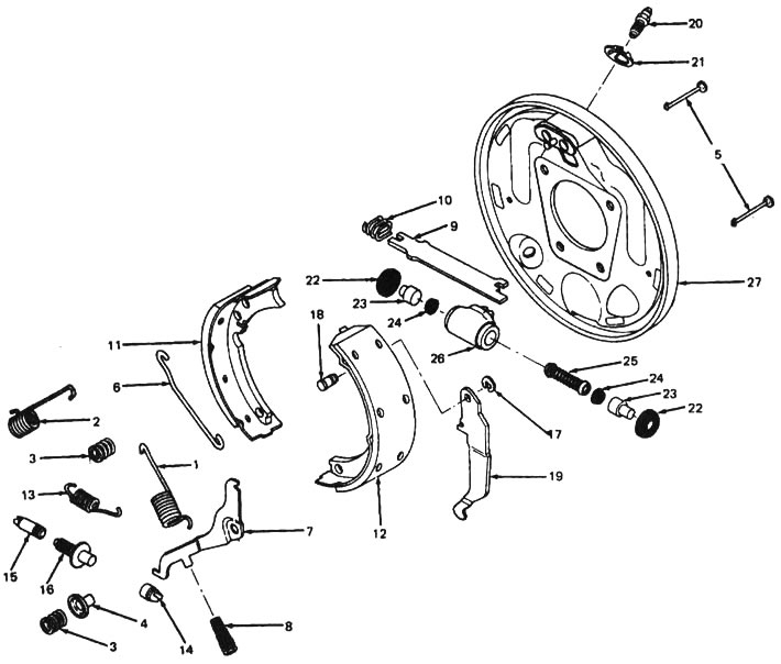
5.4v. Drum brake system parts (cars produced in 1990 and 1991.): 1 - return spring, 2 - return spring, 3 - retaining spring, 4 - lever axis, 5 - retaining pin, 6 - limiter, 7 - drive lever, 8 - lever return spring, 9 - spacer bar, 10 - bar spring, 11 - primary shoe, 12 - secondary shoe, 13 - adjusting screw spring, 14 - head, 15 - bushing, 16 - adjusting screw, 17 - snap ring, 18 - stud, 19 - parking brake lever, 20 - bleed valve, 21 - cylinder lock, 22 - protective cover, 23 - piston, 24 - cuff, 25 - spring, 26 - working brake cylinder, 27 - brake shield
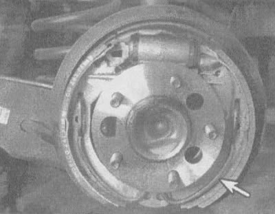
5.4g. Cars produced in 1992 and later have one conical spring (indicated by the arrow) |
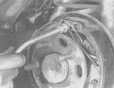
5.4d. Using a special tool for extracting brake springs, remove the return springs (for cars produced in 1990 and 1991.) |
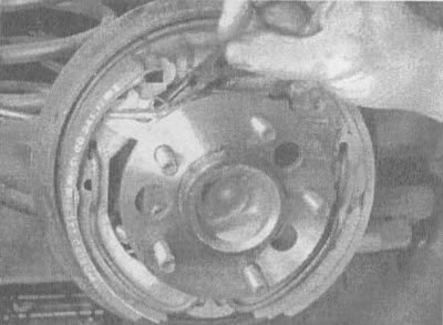
5.4e. Using small pliers, remove the retaining springs and axles by pressing and turning them (indicated by arrows) (cars produced in 1990 and 1991.) |

5.4g. Remove the retaining (pressing) springs and pins by pressing with pliers and turning (indicated by the arrow) (cars produced in 1990 and 1991.) |
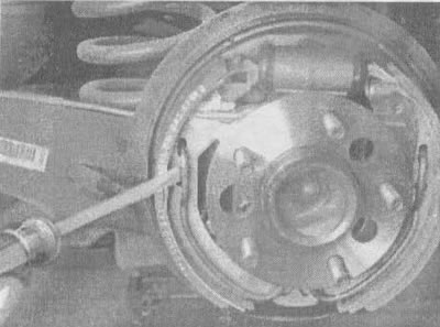
5.4z. Insert a flat-head screwdriver under the spring and press the spring out of the primary shoe, then remove the shoe (cars produced in 1992) |
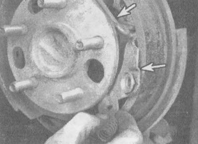
5.4i. Raise the parking brake lever up (cars produced in 1990 and 1991.) and remove it from the axle together with the return spring (indicated by arrows) |
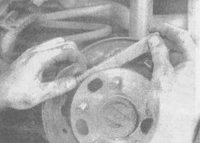
5.4k. Remove the spacer bar (for all models). On 1992 vehicles, also unscrew the adjusting screw, remembering the direction in which it is installed |
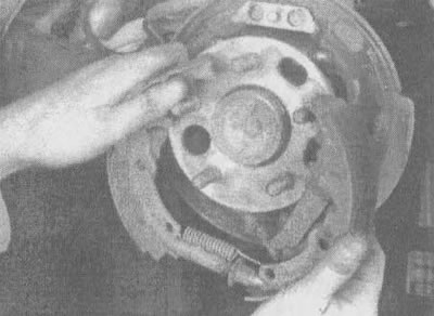
5.4L. Stretching the pads to release the hub flange, remove it from the brake shield (for cars produced in 1990 and 1991) |
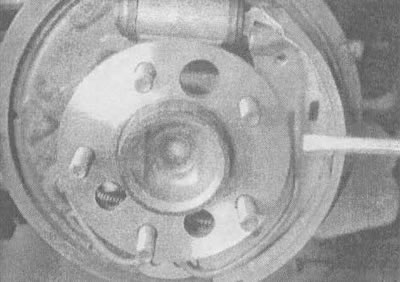
5.4m. On 1992 vehicles, lift the spring off the rear brake shoe and remove the shoe from the hub area to gain access to the parking brake cable |
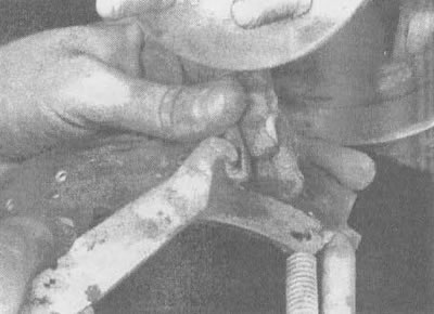
5.4n. Disconnect the parking brake lever from the cable and remove the pads (cars produced in 1990 and 1991.) |
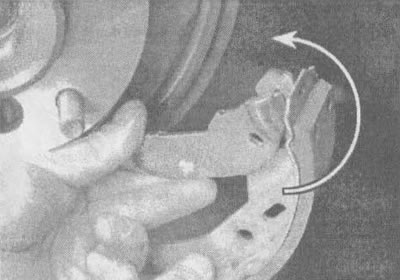
5.4o. On 1992 vehicles, rotate the brake shoe to release the parking brake lever from the shoe |
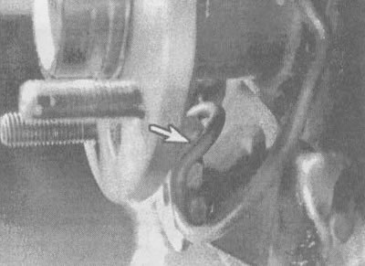
5.4p. On cars produced since 1992, use a screwdriver to remove the tension spring (indicated by the arrow). When installing new pads on these vehicles, first perform steps 5.4u and 5.4f, then reverse the removal steps and proceed to step 5.4g |
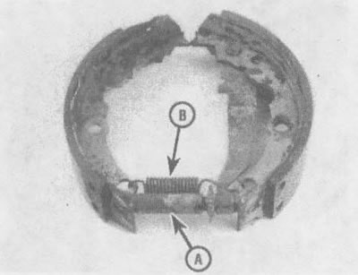
5.4p. Loosen the adjusting screw (A) and remove the spring (B) from the pads, pay attention to the position in which they are installed (cars produced in 1990 and 1991.) |
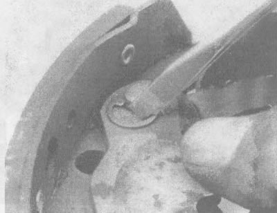
5.4c. On 1990 and 1991 vehicles, remove the parking brake lever by unhooking the C-clip |
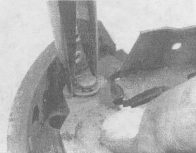
5.4t. Install the parking brake lever onto the new brake shoe and slide the C-clamp into place (cars produced in 1990 and 1991.) |
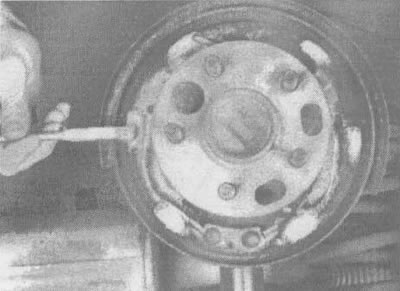
5.4u. Lubricate the contact surfaces of the brake shield with white lithium-based grease (cars of all models) |
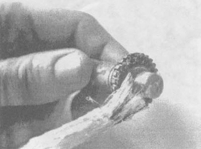
5.4f. Lubricate the adjusting screw with white lithium-based grease before screwing it in (all models) |
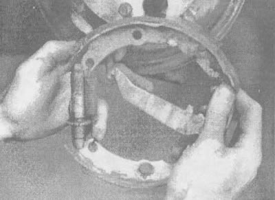
5.4x. Connect the parking brake lever to the cable (cars produced in 1990 and 1991.) |
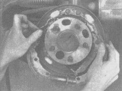
5.4c. Stretch the pads so that the hub flange passes through them and insert the pads into place (cars produced in 1990 and 1991.) |
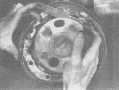
5.4h. Insert the parking brake bar and spring (cars produced in 1990 and 1991.) |
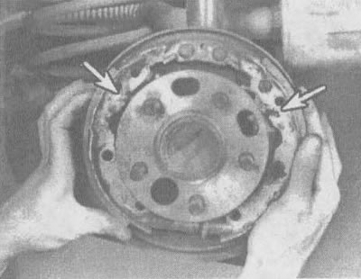
5.4sh. Check if the parking brake bar is positioned correctly in the pads (indicated by arrows) |
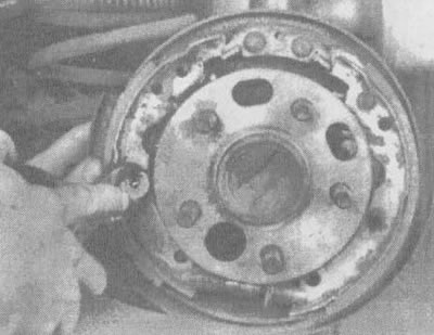
5.4 shch. Install the locking pin and spring on the primary brake pad (cars produced in 1990 and 1991.) |
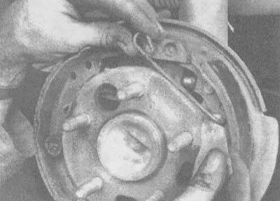
5.4th. Install the limiter and lever on the secondary brake shoe (cars produced in 1990 and 1991.) |
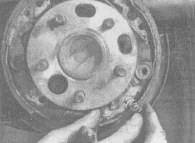
5.4aa. Insert the lever return spring (cars produced in 1990 and 1991.) |
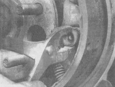
5.4ab. Screw the retaining pin and spring into the secondary brake shoe (cars produced in 1990 and 1991.) |

5.4av. Put on the return springs (cars produced in 1990 and 1991.) |
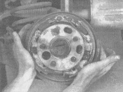
5.4ag. Center the brake shoes so that the drum slides over them (for all models) |
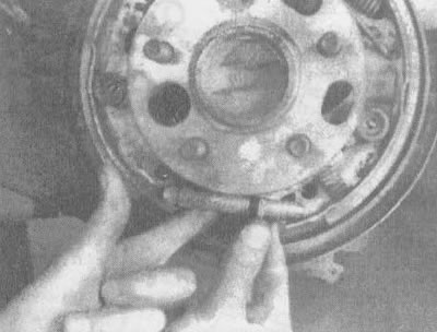
5.4ad. Adjust the adjusting nut so that the drum fits onto the pads with a little effort (for all models) |
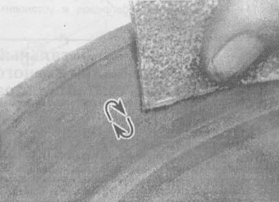
5.4a. Remove polished ("glazed") areas from the surface of the brake drum with fine-grained sandpaper, working the surface in a circular motion
5. Before replacing the drum, check for cracks, burrs, deep grooves and hardened areas, which appear as small discolored areas. If such areas cannot be removed with sandpaper or any of the other above mentioned problems are observed, the drum will have to be taken to a workshop.
Note: It is recommended that drums be re-ground regardless of their surface appearance, as this will produce a perfectly round drum and eliminate any pedal pulsation or other problems associated with a brake drum that had defects. If you decide not to resand your drums, at least remove the polish ("glaze") from the surface using medium-grit sandpaper, working the drum in a circular motion. The maximum wear disc diameter is cast on each brake drum (see illustration).
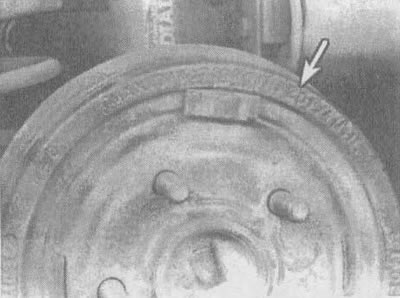
5.5. The maximum permissible diameter is cast on the drum (indicated by the arrow), which is the wear limit size, not the size at which regrinding is still permissible
6. Install the brake drum onto the axle flange.
7. Put on the wheel, tighten the wheel nuts, then lower the car. Tighten the nuts to the torque specified in the specifications in this chapter.
8. Perform several forward and reverse braking applications to adjust the brakes until you achieve satisfactory pedal action when braking.
[The original material is located on the website: ChevyMan]