Necessary equipment
- KM-470-B Angular Torque Indicator
- DW 110–060 Engine clamping fixture
Removal procedure
1. Remove the fuel pump fuse.
2. Start the engine. After the engine stops, crank the engine for 10 seconds to relieve pressure in the fuel system.
3. Disconnect the negative battery cable.
4. Drain the engine coolant. See Section 1D2, Engine Cooling System - FAM II 2.4D.
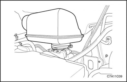
5. Remove the air cleaner assembly. See "Air filter assembly" in this section.
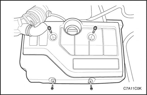
6. Remove the engine trim cover and engine trim cover bracket.
7. Disconnect the breather hose and the positive crankcase ventilation hose from the cylinder head cover.
8. Loosen the clamp and remove the resonator from the electronic throttle body.
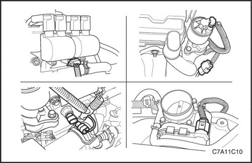
9. Disconnect the direct ignition system (DIS) connector.
10. Disconnect the oxygen sensor control connector.
11. Disconnect the electronic throttle control (ETC) unit connector.
12. Disconnect the coolant temperature sensor (CTS) connector.
13. Disconnect the exhaust gas recirculation (EGR) valve connector.
14. Remove the right front wheel. Follow section 2E, Tires and Wheels.
15. Remove the front engine shield from the right front wheel side.
16. Remove the flexing accessory drive belt. See "Auxiliary Drive Belt" in this section.
17. Install the engine assembly clamping fixture DW110-060.
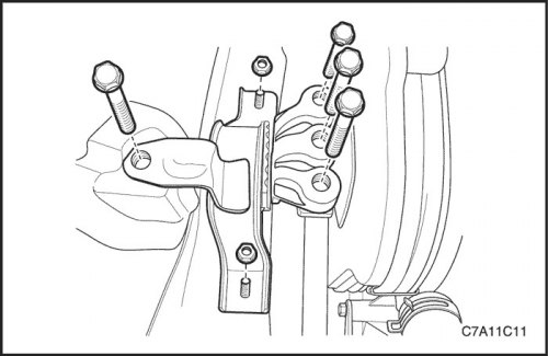
18. Remove the engine mount assembly. See "Engine mount unit" in this section.
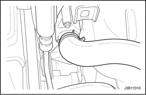
19. Disconnect the upper radiator hose from the thermostat housing.
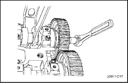
20. Remove the crankshaft pulley bolts.
21. Remove the crankshaft pulley.
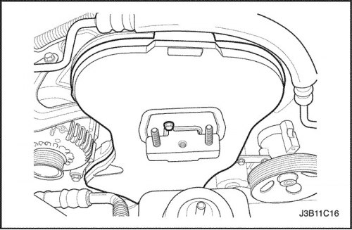
22. Remove the front timing belt cover screws
23. Remove the front timing belt cover
24. Remove the timing belt. Follow step "Gas distribution mechanism drive belt" in this section.
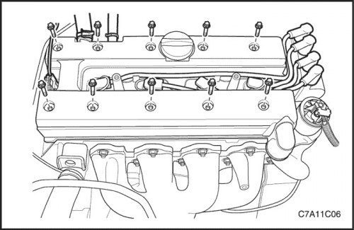
25. Remove the cylinder head cover and gasket. See "Cylinder head cover" in this section.
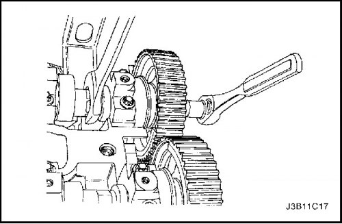
Note: Use extreme care to avoid scratching, denting or damaging the camshafts.
26. While holding the intake camshaft firmly, remove the intake camshaft gear bolts.
27. Remove the intake camshaft gear.
28. While holding the exhaust camshaft firmly, remove the exhaust camshaft gear bolts.
29. Remove the exhaust camshaft gear.
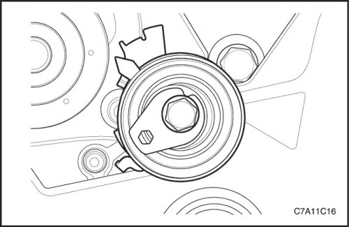
30. Remove the timing belt automatic tensioner bolts.
31. Remove the automatic timing belt tensioner.
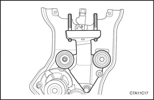
32. Remove the timing belt idler pulley screw and nut.
33. Remove the timing belt idler pulley.
34. Remove the engine mount adapter support bracket bolts.
35. Remove the engine mount adapter support bracket.
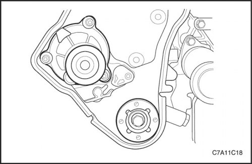
36. Remove the crankshaft gear.
37. Remove the camshaft position (CMP) sensor.
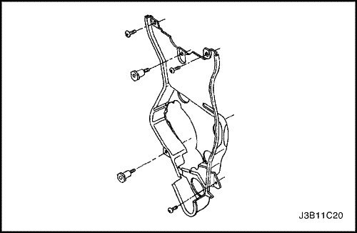
38. Remove the timing belt cover screws.
39. Remove the rear timing belt cover.
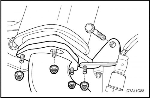
40. Unscrew the nuts securing the catalytic converter to the exhaust pipe.
41. Remove the bolt and nut from the exhaust pipe mounting bracket.
42. Remove the exhaust pipe from the catalytic converter. See Section 1G2, Exhaust System - FAM II 2.4D.
43. Disconnect all necessary vacuum hoses.
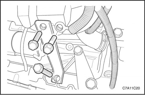
44. Loosen the intake manifold support bracket bolts and remove the bracket.
45. Remove the ground terminal retaining bolt from the intake manifold.
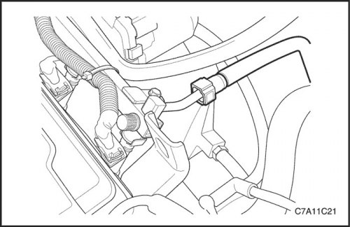
46. Disconnect the fuel supply line from the fuel rail.
47. Disconnect the coolant hoses from the rear cylinder head and the exhaust gas recirculation (EGR) valve adapter.
48. Disconnect the coolant hoses from the electronic throttle body.
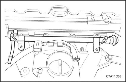
49. Remove the fuel rail assembly. See Section 1F2, Engine Controls - FAM II 2.4D.
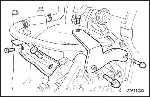
50. Unscrew the bolts of the upper generator bracket.
51. Remove the upper generator bracket.
52. Loosen the bolts of the generator mounting bracket to the intake manifold on the generator and intake manifold.
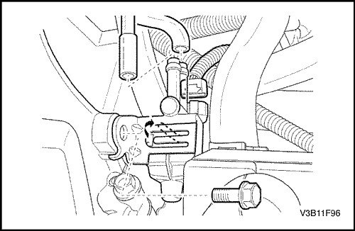
53. Unscrew the bracket bolt of the electromagnetic valve for purging the EGR canister.
54. Remove the purge valve of the SUPB adsorber.
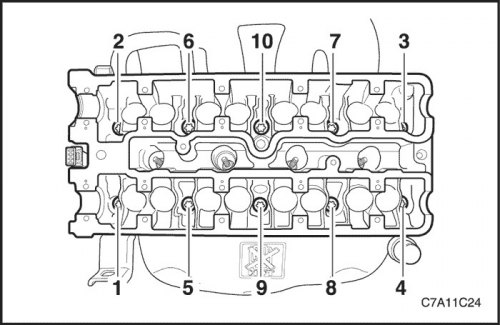
55. Remove the camshaft. See "Camshaft" in this section.
56. Gradually and in the specified sequence, loosen all cylinder head screws.
57. Remove the cylinder head bolts.
58. Remove the cylinder head with the intake and exhaust manifold attached.
Note: Do not allow engine oil or coolant to enter the cylinders when removing the cylinder head.
59. Remove the cylinder head gasket.
Cleaning procedure
1. Clean the cylinder head and cylinder block gasket surfaces.
2. Make sure that the cylinder head gasket and cylinder block surfaces are free of dents and deep scratches.
3. Clean the cylinder head bolts.
4. Check the cylinder head for warpage. Follow step "Cylinder Head and Valve Train Parts" in this section.
Installation procedure
Important: Before installing the cylinder head, be sure to install the engine mount and then remove the engine assembly clamping fixture DW110-060.
1. Install a new cylinder head gasket.
2. Install the cylinder head with the intake and exhaust manifold attached.
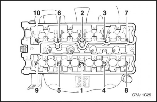
3. Install the cylinder head bolts and tighten them gradually in the sequence shown.
Tighten
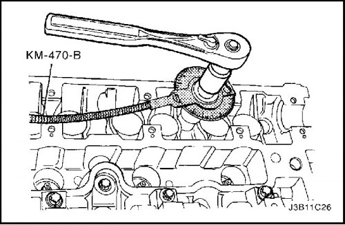
Tighten the cylinder head bolts to 25 N·m (18 lb-ft) and turn the bolts an additional 3 90° turns using the KM-470-B angular torque gauge.
4. Install the camshaft. See "Camshaft" in this section.
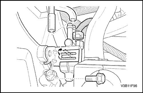
5. Install the purge valve of the SUPB adsorber.
Tighten
Tighten the canister purge solenoid valve support bracket bolt to 5 N·m (44 lb-in.).
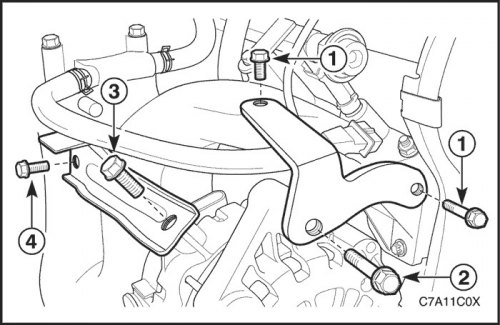
6. Install the upper generator bracket.
Tighten
Tighten the generator upper bracket retaining bolts (1) to 25 N·m (18 lb-ft) and the bolt (2) to 35 N·m (26 lb-ft).
7. Install the generator mounting bracket to the intake manifold.
Tighten
Tighten the generator to intake manifold mounting bracket retaining bolt (3) to 35 N·m (26 lb-ft) and the bolt (4) to 25 N·m (18 lb-ft).
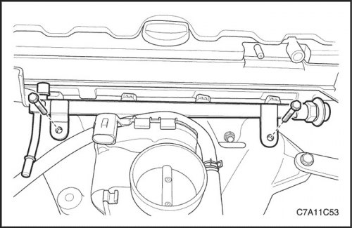
8. Connect the coolant hoses to the electronic throttle body, rear cylinder head, and EGR valve bracket.
9. Install the fuel rail assembly. See Section 1F2, Engine Controls - FAM II 2.4D.
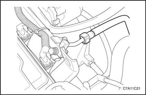
10. Connect the fuel supply line to the fuel rail.
11. Connect all necessary vacuum hoses.
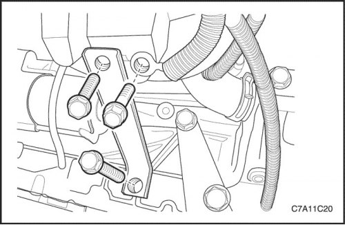
12. Tighten the ground terminal locking bolt.
13. Install the intake manifold support bracket.
Tighten
Tighten the intake manifold support bracket bolts to 25 N·m (18 lb-ft).
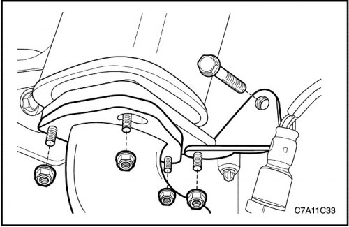
14. Install the exhaust pipe onto the catalytic converter. See Section 1G2, Exhaust System - FAM II 2.4D.
Tighten
Tighten the catalytic converter-to-exhaust pipe retaining nuts to 35 N·m (26 lb-ft).
Tighten the exhaust pipe mounting bracket bolt and nut to 40 N·m (30 lb-ft).
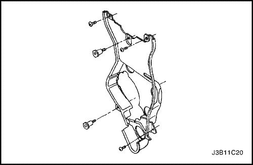
15. Install the rear timing belt cover.
Tighten
Tighten the rear timing belt cover bolts to 7 N·m (62 lb-in.).
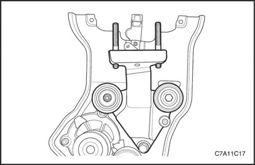
16. Install the engine mount adapter support bracket.
Tighten
Tighten the engine mount adapter support bracket retaining bolts to 45 N·m (33 lb-ft).
17. Install the timing belt idler pulleys.
Tighten
Tighten the timing belt idler pulley retaining bolt and nut to 25 N·m (18 lb-ft).
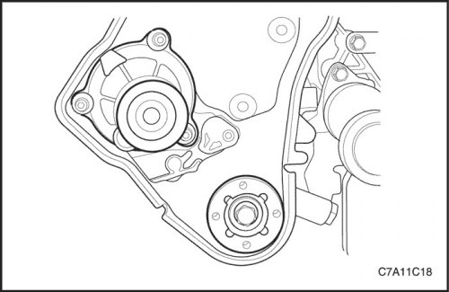
18. Install the camshaft position sensor. See Section 1F2, Engine Controls - FAM II 2.4D.
19. Install the crankshaft gear.
Tighten
Tighten the crankshaft timing belt pinion bolt to 135 N·m (100 lb-ft) and turn the bolt an additional 30° and 10° using an angular torque gauge.
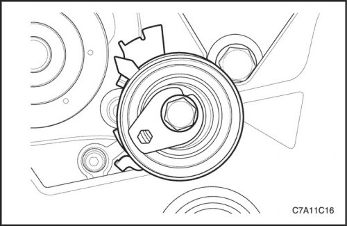
20. Install the automatic timing belt tensioner.
Tighten
Tighten the timing belt automatic tensioner retaining bolt to 25 N·m (18 lb-ft).
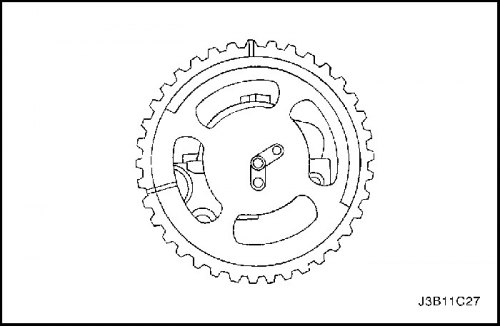
21. Install the camshaft gears with the timing marks on the front.
22. Insert the intake camshaft guide pin into the "IN" hole.
23. Insert the exhaust camshaft guide pin into the "EX" hole.
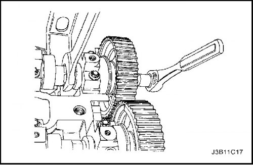
24. Install the camshaft gears by holding the camshaft hex head with an open-end wrench.
25. While holding the intake camshaft firmly, install the new intake camshaft gear bolt.
Tighten
Tighten the intake camshaft gear bolt to 50 N·m (37 lb-ft) and tighten it an additional 60° and 15° using an angular torque indicator.
26. While holding the exhaust camshaft firmly, install a new exhaust camshaft gear bolt.
Tighten
Tighten the exhaust camshaft gear bolt to 50 N·m (37 lb-ft) and rotate it an additional 60° and 15° with an angular torque indicator.
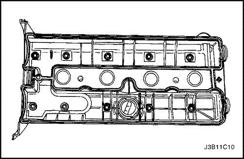
27. Apply a small amount of sealant to the corners of the front camshaft head and where the top of the rear cylinder head cover attaches to the cylinder head gasket.
28. Install the cylinder head cover gasket and the cylinder head cover. See "Cylinder Head Cover and Gasket" in this section.
Tighten
Tighten the cylinder head cover bolts to 8 N·m (71 lb-in.).
29. Connect the spark plug wires to the spark plugs.
30. Connect the breather hose and the positive crankcase ventilation hose to the cylinder head cover.
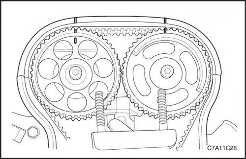
31. Align the timing marks on the camshaft gears with the notches on the cylinder head, using the intake gear mark for the intake gear and the exhaust gear mark for the exhaust gear.
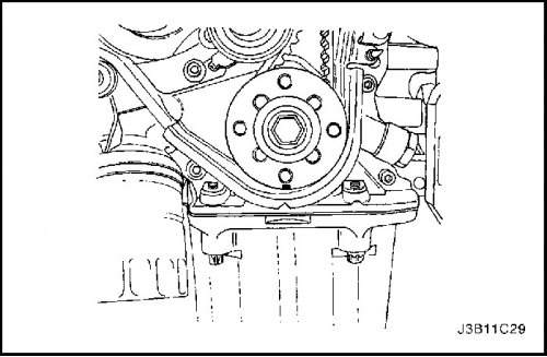
32. Align the mark on the crankshaft gear with the notch on the bottom of the timing belt cover.
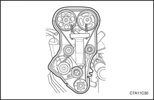
33. Install the timing belt of the gas distribution mechanism.
34. Check and adjust the timing belt tension. See "Checking and adjusting the timing belt tension" "Checking and adjusting the tension of the timing belt" in this section.
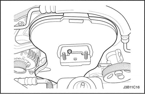
35. Install the front timing belt cover.
Tighten
Tighten the front timing belt cover retaining bolts to 6 N·m (53 lb-in.).
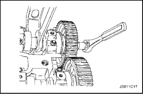
36. Install the crankshaft pulley.
Tighten
Tighten the crankshaft pulley bolts to 23 N·m (17 lb-ft).
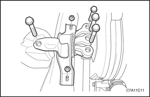
37. Install the engine mount assembly. See "Engine mount assembly" in this section.
Tighten
Tighten the engine mount adapter bolts to 50 N·m (11 lb-ft).
Tighten the engine mount side frame bracket bolt to 100 N·m (74 lb-ft) and the nuts to 90 N·m (66 lb-ft).
38. Remove the engine assembly fixture DW110-060.
39. Install the flexing accessory drive belt. See "Auxiliary Drive Belt" in this section.
40. Connect the upper radiator hose to the thermostat housing.
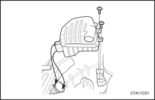
41. Install the front engine shield on the right front wheel side.
42. Install the right front wheel. Follow section 2E, Tires and Wheels.
43. Install the air cleaner assembly. See "Air filter assembly" in this section.
Tighten
Tighten the air cleaner housing bolts to 10 N·m (89 lb-in.).
44. Connect the IAT sensor connector.
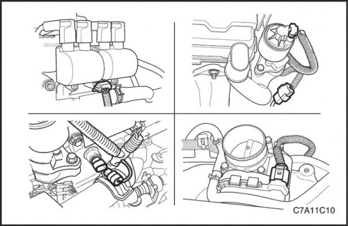
45. Connect the coolant temperature sensor (CTS) connector.
46. Connect the electronic throttle control (ETC) sensor connector.
47. Connect the DIS coil connector.
48. Connect the O2 sensor connector.
49. Connect the exhaust gas recirculation (EGR) valve connector.
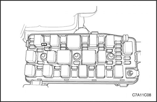
50. Install the fuel pump fuse.
51. Connect the negative battery cable.
52. Fill the engine cooling system. See Section 1D2, Engine Cooling System - FAM II 2.4D.