Contents: Disassembly procedure ↧ Checking the cylinder head ↧ Checking the valves ↧ Cleaning procedure ↧ Cylinder head overhaul ↧ Assembly procedure ↧
Necessary equipment
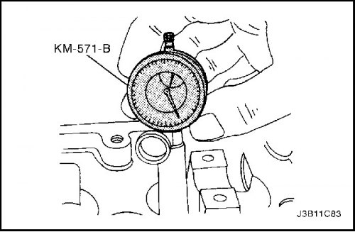
KM-571-B Measuring Instrument
KM-340-0 Cutting tool kit
KM-340-7 Guide punch
KM–340–13 Cutting tools
KM–340–26 Cutting tools
KM–348 Valve Spring Compressor
KM–653 Adapter
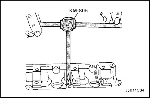
KM–805 Valve guide knob
Disassembly procedure
1. Remove the cylinder head with the intake and exhaust manifold attached. Follow step "Cylinder head and gasket" in this section.
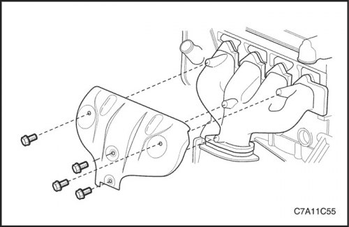
2. Remove the exhaust manifold heat shield.
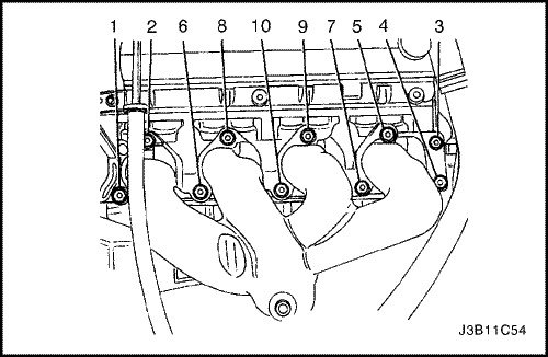
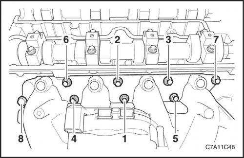
3. Remove the exhaust manifold retaining nuts in the sequence shown.
4. Remove the exhaust manifold.
5. Remove the exhaust manifold gasket.
6. Remove the exhaust manifold pin.

7. Remove the thermostat housing mounting screws.
8. Remove the thermostat housing assembly.
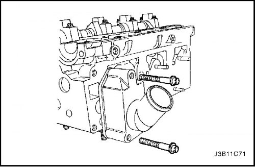
9. Remove the coolant bypass mounting screws and housing.
10. Remove the fuel rail assembly. See Section 1F2, Engine Controls - FAM II 2.4D.
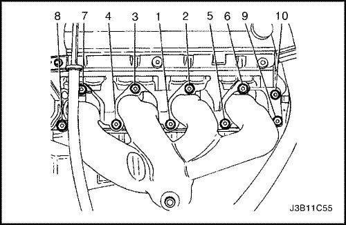
11. Remove the intake manifold retaining bolts and nuts in the following sequence.
12. Remove the intake manifold support bracket.
13. Remove the intake manifold.
14. Remove the intake manifold gasket.
15. Remove the intake manifold pin.
16. Remove the cylinder head cover. See "Cylinder Head Cover" in this section.
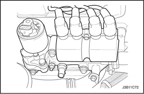
17. Remove the direct ignition system (DIS) coil and the exhaust gas recirculation (EGR) valve adapter support bolts.
18. Remove the direct ignition system (DIS) coil and the exhaust gas recirculation (EGR) valve adapter.
19. Remove the spark plugs.

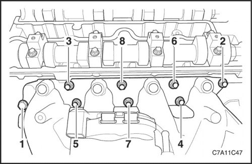
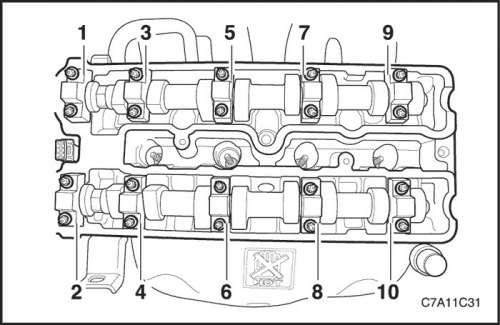
20. Gradually remove the camshaft bearing cap screws in the sequence shown for each camshaft cap.

21. Remove the intake camshaft caps. Select the correct position for installation.
22. Remove the intake camshaft.
23. Remove the intake valve lifter adjusting tools.
24. Remove the exhaust camshaft heads. Select the correct position for installation.
25. Remove the exhaust camshaft.
26. Remove the exhaust valve lifter adjusting tools.
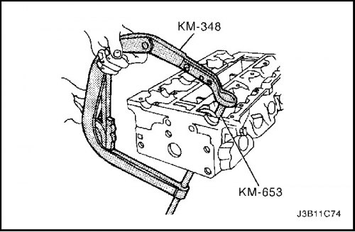
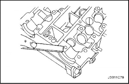
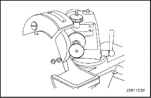
27. Compress the valve springs using the valve spring compressor KM–348 and adapter KM–653.
28. Remove the valve spring retainers.
29. Remove the valve spring compressor KM–348 and adapter KM–653.
30. Remove the valve spring covers.
31. Remove the valve springs. Select the original position for installing the valve springs.
32. Remove the valves. Select the original position for valve installation.
Checking the cylinder head
1. Clean the sealing surfaces.
2. Check the cylinder head as follows.
- Are there any cracks, damage or chipping of the ignition chamber surface?.
- Are there any foreign particles in the lubrication channels? Thoroughly clean the channels from foreign particles.
- Are there any coolant leaks or damage to the top layer of the sealing surface? · Is there any damage to the surface of any of the gaskets?.
- Is there any damage to the threaded holes of any of the bolts?.
- Are there any burnt or eroded areas in the combustion chamber?.
- Are there any cracks in the intake ports and combustion chambers?.
- Are there any external cracks in the water channels?.
- Are there any restrictions in the inlet or outlet ducts?.
- Are there any restrictions in the cooling system flow?.
- Are there any rusty, damaged or leaking plugs?.
3. If cracks or damage are found on the cylinder head, it must be replaced. It is not recommended to carry out welding work on the cylinder head or repair damage.
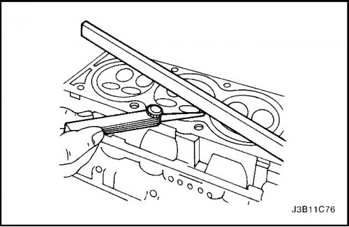
4. Measure the gap between the straightedge and the face of the cylinder head at four points along the straightedge using a gap gauge.
5. Check the sealing surfaces for deformation and distortion. The flatness of the cylinder head sealing surfaces should be no more than 0.025 mm (0.001 inches).
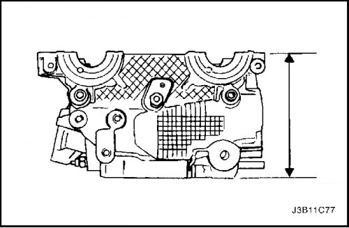
6. Measure the height of the cylinder head from sealing surface to sealing surface. The height of the cylinder head should be between 133.975 and 134.025 mm (from 5.274 to 5.276 inches). If the cylinder head height is less than 133.9 mm (5.271 inches), the cylinder head needs to be replaced.
Checking the valves
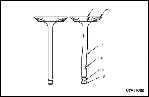
1. Check for valve damage from head to stop as follows.
- Is there any surface chipping in the valve seat area (1)
- Is the valve edge (2) the correct shape?
- Is there a bend in the valve stem (3)
- Is there any surface chipping or excessive wear in the piston rod (4)
- Are the valve key grooves worn out (5)?
- Is the valve stop (6) worn out?
2. Replace the valve if any of these signs occur.
3. Check the valve springs. If the end of the valve spring is not parallel, replace the valve spring.
4. Check the valve seat for wear or chipping. Replace if necessary.
Cleaning procedure
1. Clean the cylinder head.
2. Clean the valve guides.
3. Clean all threaded holes.
4. Clean the valves from soot, oil and carbon deposits.
Cylinder head overhaul
Valve grinding
1. Lubricate the valve seat with fine-grained paste.
2. Use a commercially available valve grinding tool to lift the valve evenly off the seat to distribute the paste.
3. Check the contact pattern on the valve head and cylinder head.
4. Clean the valves, valve guides and cylinder head.
Valve sharpening
1. Make sure there are no burns on the valve plate cone.
2. The valve can be re-sharpened no more than twice. Do not sharpen the end of the valve stem.
3. Make sure the valve bevel angle is 45 degrees.
4. Check the height of the intake and exhaust valve block.
Valve guide reaming
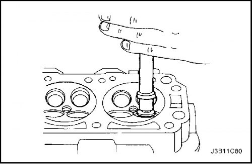
1. Measure the valve guide diameter using the MKM-571-B gauge and a commercially available inside micrometer.
Important: Oversize valves may have already been adjusted at the factory.
2. The oversize code is located on the valve guide and the end of the valve stem. The following table gives the correct dimensions, bore, and production code for each service.
| Size | Scan | Production code | Service code |
| ordinary | - | - | TO |
| 0,075 | KM-805 | 1 | K1 |
| 0,150 | - | 2 | K2 |
3. Ream the valve guide from the top of the cylinder head to the next oversize.
4. After boring, cross out the code and stamp a new code on the valve guide.
Valve seat machining
1. Place the cylinder head on a wooden block.
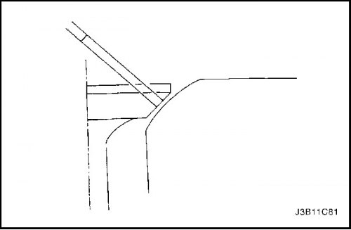
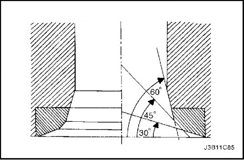
2. Cut the intake and exhaust valve seats using punch KM–340–7 as follows:
- Valve seat - 45° surface using cutting tool KM–340–13.
- Upper correction angle - 30° surface using cutting tool KM–340–13.
- Lower correction angle - 60° surface using cutting tool KM–340–26.
3. Clean the chips from the cylinder head.
4. Check the dimension for valve seat width.
- Intake: from 1.2 to 1.4 mm (0.047 - 0.055 inches)
- Issue: from 1.4 to 1.8 mm (0.055 - 0.070 inches)
5. Check the height of the intake and exhaust valve block. If the size is exceeded, install new valves. Check the block height again. If the block height is still higher despite replacing the valves, replace the cylinder head.

Assembly procedure
1. Lubricate the valve stems with engine oil.
2. Carefully return the valves to their original positions.
3. Install the valve springs to their original position.
4. Install the valve spring caps.
5. Compress the valve springs using the valve spring compressor KM–348 and adapter KM–653.
6. Install the valve wedges.
7. Remove the valve spring compressor KM–348 and adapter KM–653.
8. Lubricate the valve lifter adjustment tools with engine oil.
9. Install the valve lifter adjustment tools.
10. Install the intake camshaft.
11. Install the intake camshaft bearing caps to their original positions.
12. Install the exhaust camshaft.
13. Install the exhaust camshaft bearing caps to their original positions.
14. Install the camshaft bearing cap bolts gradually in the sequence shown for each camshaft cap.
Tighten
Tighten the camshaft bearing cap bolts to 8 N·m (71 lb-in.).

15. Install the spark plugs.
Tighten
Tighten the spark plugs to 25 N·m (18 lb-ft).
16. Install the direct ignition system (DIS) coil and exhaust gas recirculation (EGR) valve adapter.
Tighten
Tighten the ignition coil and EGR valve adapter retaining bolts to 25 N·m (18 lb-ft).
17. Install the intake manifold pins.
18. Install the intake manifold gasket.
19. Install the intake manifold.
20. Install the intake manifold retaining bolts and nuts in the sequence shown below.
Tighten
Tighten the intake manifold retaining bolts and nuts to 22 N·m (16 lb-ft).
21. Install the intake manifold support bracket.
Tighten
Tighten the intake manifold support bracket bolts to 25 N·m (18 lb-ft).
22. Install the fuel rail assembly. See Section 1F2, Engine Controls - FAM II 2.4D.
23. Install the thermostat housing assembly.
Tighten
Tighten the thermostat housing assembly mounting bolts to 15 N·m (11 lb-ft).
24. Install the coolant bypass housing and mounting screws.
Tighten
Tighten the coolant bypass housing screws to 15 N·m (11 lb-ft).
25. Install the exhaust manifold pins.
26. Install the exhaust manifold gasket.
27. Install the exhaust manifold.
28. Install the exhaust manifold lock nuts in the sequence shown.
Tighten
Tighten the exhaust manifold lock nuts to 22 N·m (16 lb-ft).

29. Install the exhaust manifold heat shield.
Tighten
Tighten the exhaust manifold heat shield bolts to 8 N·m (71 lb-in).
30. Install the cylinder head with the intake and exhaust manifold attached. Follow step "Cylinder head and gasket" in this section.