Contents: Disassembly procedure ↧ Assembly procedure ↧
Necessary equipment
DW100-030 Engine Overhaul Stand
KM-470-B Angular Torque Indicator
J–36972 or KM–635 Rear Crankshaft Oil Seal
Note: Use extreme care to avoid scratching, denting or damaging the camshafts.
Disassembly procedure
1. Remove the engine. Follow the step "Engine" in this section.
2. Remove the flywheel or flexplate screws.
3. Remove the flywheel or flexplate.
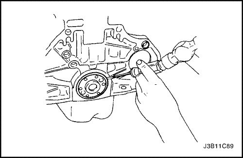
4. Remove the rear crankshaft oil seal.
5. Install the engine on the DW100-030 engine overhaul stand.
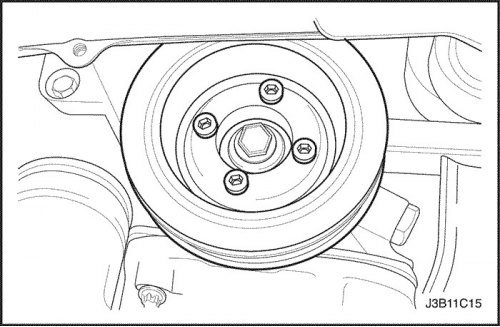
6. Remove the crankshaft pulley bolts.
7. Remove the crankshaft pulley.
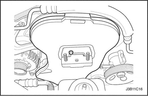
8. Remove the front timing belt cover screws
9. Remove the front timing belt cover
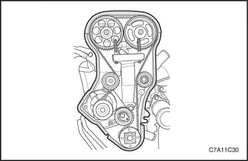
10. Loosen the timing belt automatic tensioner screw.
11. Turn the hexagonal head of the timing belt automatic tensioner clockwise to loosen the tension.
12. Remove the timing belt idler pulley screw and nut.
13. Remove the timing belt idler pulleys.
14. Remove the drive belt of the gas distribution mechanism.
15. Remove the engine mount adapter support bracket bolts.
16. Remove the engine mount adapter support bracket.
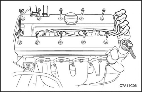
17. Remove the spark plug wires from the spark plugs.
18. Remove the cylinder head cover and gasket. See "Cylinder head cover" in this section.
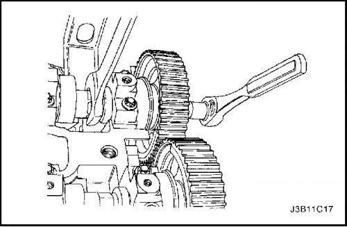
Note: Use extreme care to avoid scratching, denting or damaging the camshafts.
19. While holding the intake camshaft firmly, remove the intake camshaft gear bolt.
20. Remove the intake camshaft gear.
21. While holding the exhaust camshaft firmly, remove the exhaust camshaft gear bolt.
22. Remove the exhaust camshaft gear.
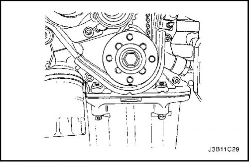
23. Remove the crankshaft gear.
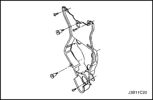
24. Loosen the timing belt rear cover bolts and remove the cover.
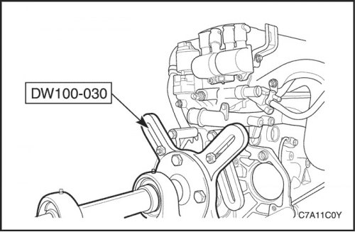
25. Rotate the engine on the DW100-030 engine overhaul stand.
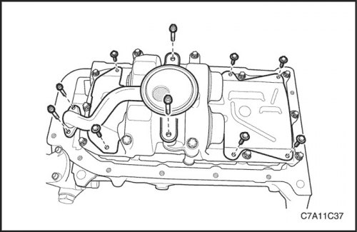
26. Remove the oil pan retaining screws.
27. Remove the oil pan.
28. Remove the oil suction pipe screws.
29. Remove the oil suction pipe with the sealing ring.
30. Remove the oil pan scraper bolts.
31. Remove the oil pan scrapers.
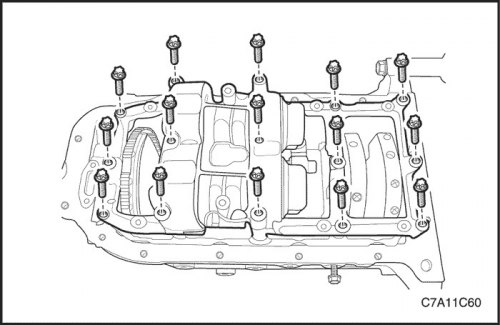
32. Loosen the crankshaft balancer assembly lock bolts.
33. Remove the crankshaft balancer assembly.
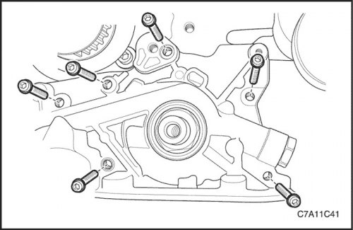
34. Remove the oil pump retaining screws.
35. Remove the oil pump.
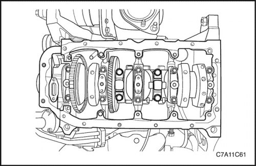
36. Record the sequence for installing the connecting rod bearing caps.
37. Remove the connecting rod bearing cap screws for all pistons.
38. Remove the connecting rod bearing caps and lower the connecting rod bearings.
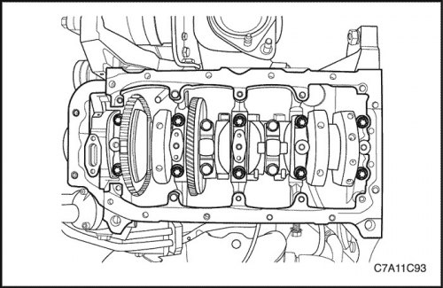
39. Record the sequence for installing the crankshaft bearing caps.
40. Remove the main bearing cap screws.
41. Remove the main bearing caps and lower main bearings.
42. Remove the crankshaft.
43. Clean parts if necessary.
Assembly procedure
1. Lubricate the main bearings with engine oil.
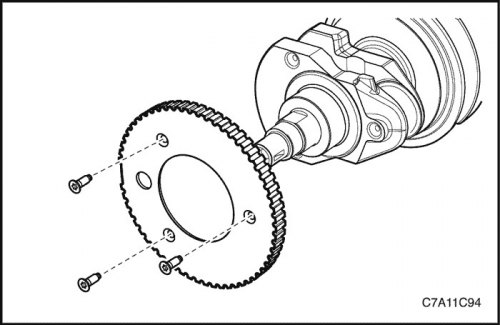
2. When replacing the crankshaft, transfer the timing gear to the new crankshaft.
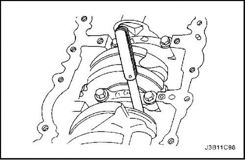
3. Install the crankshaft.
4. Install the lower main bearings into the bearing caps.
5. Check the crankshaft axial clearance with the main bearings installed.
6. Check the permissible axial clearance of the crankshaft. Follow the point "Engine Specifications" in this section.
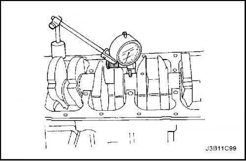
7. When the crankshaft is installed in the front and rear main bearings, check the crankshaft center journal for permissible eccentricity (runout). Follow step "Engine Specifications" in this section.
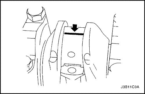
Important: Lubricate the crankshaft journals with grease and lightly lubricate the main bearings to prevent the plastic gauging wire from coming off when removing the main bearing caps.
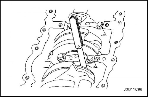
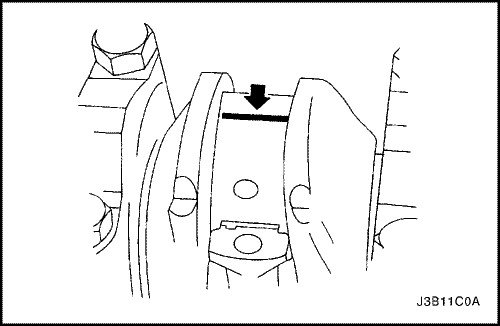
8. Check all main bearing clearances using a commercially available plastic gauging wire (elastic calibration wire).
9. Cut a plastic gauging wire to the same size as the bearing width. Place it axially between the crankshaft journals and the main bearings.
10. Install the main bearing caps and screws.
Tighten
Tighten the main bearing cap bolts to 50 N·m (37 lb-ft) plus 45° and 15°.
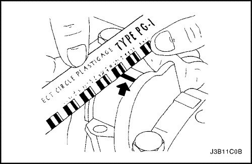
11. Remove the main bearing cap screws and covers.
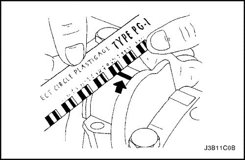
12. Measure the width of the flattened plastic gauging wire using a ruler. (Plastic calibration wire is available for different tolerances).
13. Check the bearing clearances for permitted tolerances. Follow step "Engine Specifications" in this section.
14. Apply a bead of adhesive sealant to the main bearing cap grooves.
15. Install the main bearing caps onto the cylinder block.
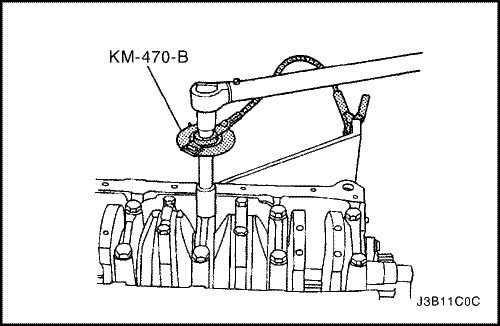
16. Tighten the main bearing caps using new screws.
Tighten
Tighten the main bearing cap bolts to 50 N·m (37 lb-ft) using a torque wrench. Using the KM-470-B angular torque gauge, tighten the main bearings an additional 45° and 15°.
Important: Lubricate the connecting rod bearing journals and lightly lubricate the connecting rod bearings to prevent the plastic gauging wire from coming off when removing the connecting rod bearing caps.
17. Check all connecting rod bearing clearances using a commercially available plastic gauging wire (elastic calibration wire).
18. Cut a plastic gauging wire to the same size as the connecting rod bearing width. Place it axially between the connecting rod journals and the connecting rod bearings.
19. Install the connecting rod bearing caps.
Tighten
Tighten the connecting rod bearing cap bolts to 35 N·m (26 lb-ft) using a torque wrench. Using the KM-470-B angular torque indicator, tighten the connecting rod bearing cap bolts an additional 45° plus 15°.
20. Remove the connecting rod bearing caps.
21. Measure the width of the flattened plastic gauging wire using a ruler. (Plastic calibration wire is available for different tolerances).
22. Check the bearing clearances for permitted tolerances. Follow step "Engine Specifications" in this section.
23. Install the connecting rod bearing caps onto the connecting rods.
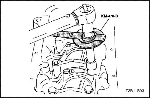
24. Tighten the connecting rod bearing caps using new screws.
Tighten
Tighten the connecting rod bearing cap bolts to 35 N·m (26 lb-ft) using a torque wrench. Using the KM-470-B angular torque indicator, tighten the connecting rod bearing cap bolts an additional 45° plus 15°.
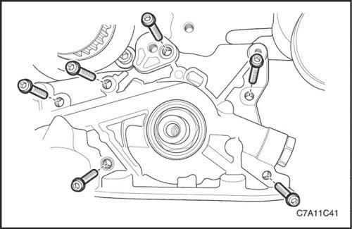
25. Install the oil pump.
26. Install the oil pump retaining screws.
Tighten
Tighten the oil pump retaining bolts to 10 N·m (89 lb-in.).
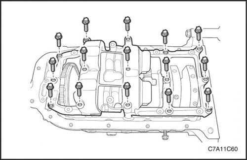
27. Install the crankshaft balancer assembly.
28. Tighten the crankshaft balancer assembly retaining bolts.
Tighten
Tighten the crankshaft balancer assembly lock bolts to 20 N·m (15 lb-ft) and turn the bolts an additional 45° using the KM-470-B angular torque gauge.
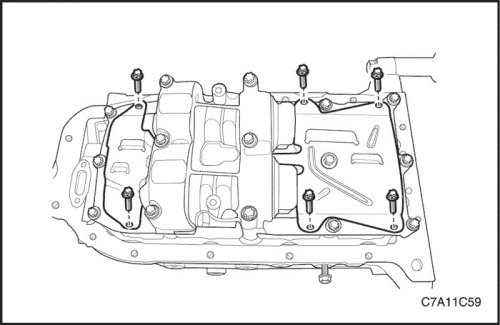
29. Install the oil pan scrapers.
30. Install the oil pan scraper retaining bolts.
Tighten
Tighten the oil pan scraper retaining bolts to 8 N·m (71 lb-in.).
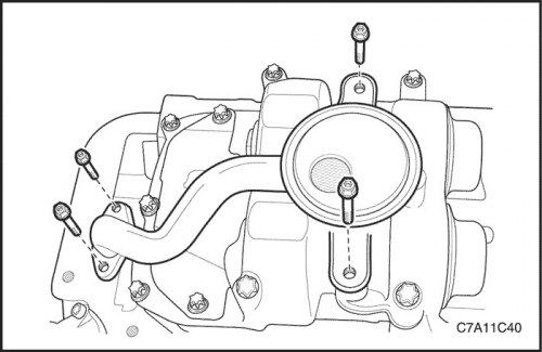
31. Install the oil suction pipe with the sealing ring.
32. Install the oil suction pipe retaining bolts.
Tighten
Tighten the oil suction pipe bolts to 8 N·m (71 lb-in.).
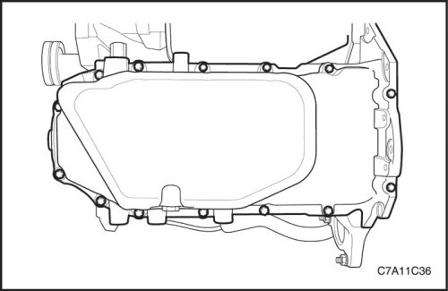
33. Apply sealant to the mating surfaces of the oil pan.
34. Install the oil pan.
35. Install the oil pan retaining screws.
Tighten
Tighten the oil pan retaining bolts to 10 N·m (89 lb-in.).
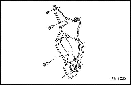
36. Rotate the engine on the DW100-030 engine overhaul stand.
37. Install the rear timing belt cover.
38. Install the timing belt rear cover screws.
Tighten
Tighten the rear timing belt cover bolts to 7 N·m (62 lb-in.).
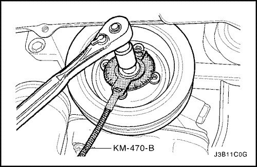
39. Install the crankshaft gear and bolt.
Tighten
Tighten the crankshaft gear bolt to 135 N·m (100 lb-ft) plus 30° plus 10° using the KM-470-B angular torque gauge.
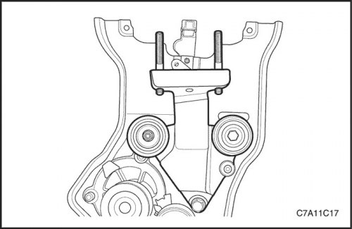
40. Install the engine mount adapter support bracket and bolts.
Tighten
Tighten the engine mount adapter support bracket retaining bolts to 45 N·m (33 lb-ft).
41. Install the timing belt idler pulley.
42. Install the timing belt idler pulley screw and nut.
Tighten
Tighten the timing belt idler pulley bolt to 25 N·m (18 lb-ft).
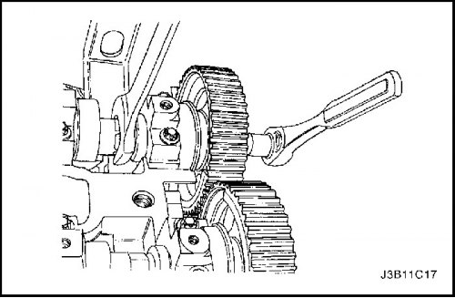
Note: Use extreme care to avoid scratching, denting or damaging the camshafts.
43. Install the intake camshaft gear.
44. While holding the intake camshaft firmly, remove the bolt and intake camshaft gear.
Tighten
Tighten the intake camshaft gear bolt to 50 N·m (37 lb-ft) plus 60° and 15° using the angular torque gauge KM-470-B.
45. Install the exhaust camshaft gear.
46. While holding the exhaust camshaft firmly, remove the bolt and exhaust camshaft gear.
Tighten
Tighten the exhaust camshaft gear bolts to 50 N·m (37 lb-ft) plus 60° and 15° using the angular torque gauge KM-470-B.
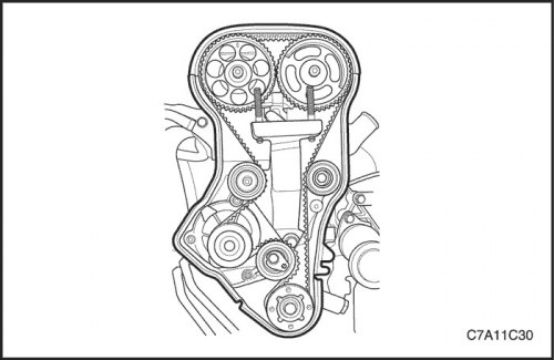
47. Install the automatic timing belt tensioner.
Tighten
Tighten the timing belt automatic tensioner bolts to 25 N·m (18 lb-ft).
48. Install the timing belt. Follow step "Gas distribution mechanism drive belt" in this section.
49. Adjust the timing belt tension. Follow step "Checking and adjusting the tension of the timing belt" in this section.
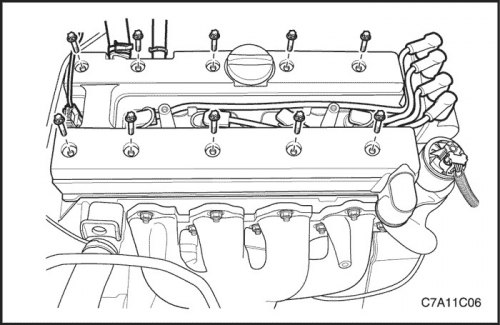
50. Apply a small amount of sealant to the corners of the front camshaft head and where the top of the rear cylinder head cover attaches to the cylinder head gasket.
51. Install the cylinder head cover gasket and the cylinder head cover gasket. Follow the step "Cylinder head and gasket" in this section.
Tighten
Tighten the cylinder head cover bolts to 8 N·m (71 lb-in.).
52. Connect the spark plug wires to the spark plugs.
53. Connect the breather and positive crankcase ventilation hose to the cylinder head cover.
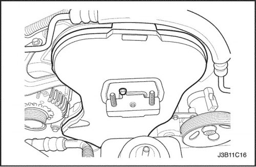
54. Install the front timing belt cover.
55. Install the front timing belt cover screws.
Tighten
Tighten the front timing belt cover bolts to 6 N·m (53 lb-in.).
56. Install a lifting device on the engine support bracket and lift the engine assembly to remove the load from the DW100-030.
57. Remove the engine from the engine overhaul stand DW100-030.
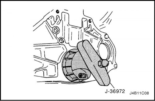
58. Install a new crankshaft rear oil seal using Crankshaft Rear Oil Seal Installer J-36792.
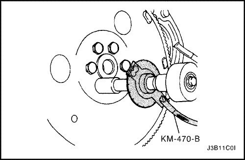
59. Install the flywheel or flex plate.
60. Install the flywheel or flexplate bolts.
Tighten
Tighten the flywheel bolts to 65 N·m (48 lb-ft).
Using the KM-470-B angular torque indicator, tighten the flywheel bolts an additional 30° plus 15°.
For automatic transaxle assembly, tighten the flexplate bolts to 45 N·m (33 lb-ft).
61. Install the engine. Follow the step "Engine" in this section.