
Removal procedure
1. Remove the oil pan. Follow step "Oil pan" in this section.
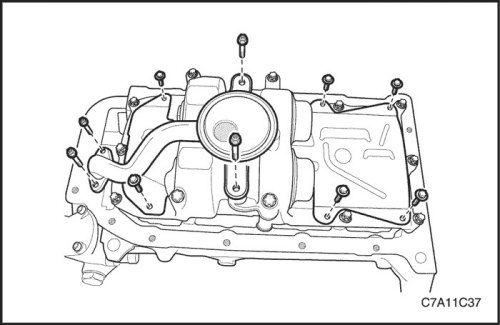
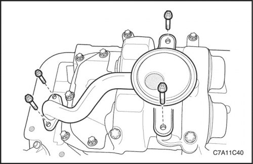
2. Remove the oil suction pipe with the sealing ring.
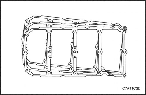
3. Remove the oil pan.

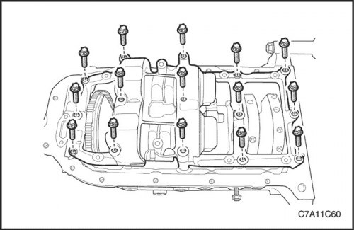
4. Loosen the crankshaft balancer assembly lock bolts.
5. Remove the crankshaft balancer assembly and the lining.

Adjustment procedure
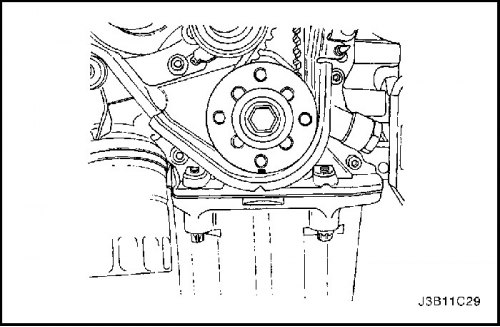
1. Align the mark on the crankshaft gear with the notch on the bottom of the timing belt cover.
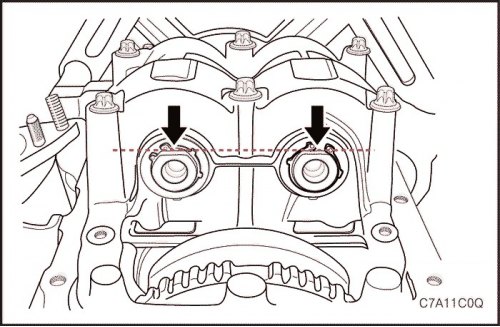
2. In this position of the crankshaft the flattened side (indicated by the arrow) both shafts of the balancing system must be facing downwards (towards the oil pan) and must be on a horizontal line.
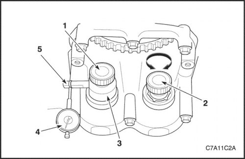
3. Screw the measuring device KM-949 (3) using a long knurled bolt (1) into the 1st shaft of the balancing system (intake side) and tighten by hand. The measuring arm (5) should be directed to "9 o'clock" as shown in the illustration.
4. Install the dial indicator holder with indicator (4) on the cylinder block.
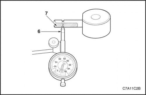
5. Place the pre-tensioned indicator head (6) on the measuring arm of the KM-949 measuring device. The head must be installed exactly between the notch marks, perpendicular to the flat surface (7).

6. Determine the left and right stops by turning the knurled bolt (2).
7. Set the indicator dial to zero.
8. Using the knurled bolt (2), move the 2nd shaft of the balancing system (release side) back and forth. Again, read the tooth clearance reading from the indicator at the same time.
9. The permissible lateral clearance between the teeth is: from 0.02 mm to 0.06 mm (from 0.0008 to 0.0024 inches).
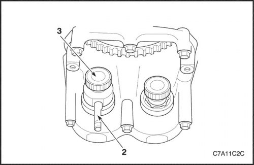
10. The side clearance between the teeth should be measured in 4 different places; additionally turn the crankshaft by the timing belt drive sprocket mounting bolt by 45° in the direction of engine rotation until the measuring arm (2) is directed to "6 o'clock".

11. Then loosen the knurled bolt (3), fix the measuring arm again at 9 o'clock and repeat the measurements.
12. If the value determined in one of the 4 measurements is outside the permissible range from 0.02 mm to 0.06 mm (from 0.0008 to 0.0024 inches), it is necessary to adjust the lateral clearance between the teeth.
13. Remove the balancer assembly from the cylinder block/main bearing caps and remove it together with the balancing piece. The balancing piece has a number (code) for easy selection. The side clearance between the teeth can be adjusted using balancing pieces of different thicknesses.
| Code | Thickness of balancing part in millimeters (mm) |
| 55 | 0,535 – 0,565 |
| 58 | 0,565 – 0,595 |
| 61 | 0,595 – 0,625 |
| 64 | 0,625 – 0,655 |
| 67 | 0,655 – 0,685 |
| 70 | 0,685 – 0,715 |
| 73 | 0,715 – 0,745 |
| 76 | 0,745 – 0,775 |
| 79 | 0,775 – 0,805 |
| 82 | 0,805 – 0,835 |
| 85 | 0,835 – 0,865 |
Each subsequent larger or smaller balancing part changes the lateral clearance between the teeth by 0.02 mm (0.0008 inches).
Example of choosing a balancing part: The installed balancing part with code "70" gave a lateral gap between the teeth of 0.08 mm (0.0031 inches). If you now install the balancing part with the code "67", the lateral clearance between the teeth will be approximately 0.06 mm (0.0024 inches).
Attention! Only one balancing part can be installed.
Installation procedure
Caution: Before installing the balance shaft assembly, perform the adjustment procedure necessary for proper operation.
Caution! Do not break or press the teeth when engaging the gear set into the assembly.
1. Align the mark on the crankshaft gear with the notch on the bottom of the timing belt cover.

2. Turn the balance shaft until the flattened side (indicated by the arrow) both shafts of the balancing system will not be facing downwards (towards the oil pan) and be on a horizontal line.
3. Install the selected balancing part together with the balance shaft assembly onto the cylinder block.
4. Tighten the locking bolts of the balance shaft assembly.
Tighten
Tighten the balancer shaft assembly lock bolts to 20 N·m (15 ft·lbs) and turn the bolts another 45° using the KM-470-B angular torque indicator.
Note: If the balance shaft assembly needs to be replaced, use the thickest balance piece code "85" for initial installation to ensure tooth backlash at all times.
5. Install the oil pan scraper.
Tighten
Tighten the oil pan scraper retaining bolts to 8 N·m (71 lbs.in).
6. Install the oil suction pipe with the sealing ring.
Tighten
Tighten the oil suction pipe retaining bolts to 8 Nm (71 lbs.in).
7. Install the oil pan. Follow the step "Oil pan" in this section.
(The original source of the article is the website «ChevyMan»)