


Contents: Removal procedure ↧ Installation procedure ↧
Removal procedure
1. Disconnect the negative battery cable.
2. Drain the engine coolant. See Section 1D2, Engine Cooling System - FAM II 2.4D.
3. Disconnect the intake air temperature (IAT) sensor connector.
4. Loosen the clamp and disconnect the air cleaner outlet hose from the electronic throttle body with the resonator attached.
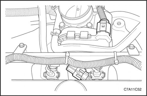
5. Disconnect the electronic throttle control (ETC) sensor connector.
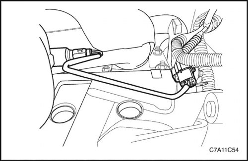
6. Disconnect the manifold absolute pressure (MAP) sensor.
7. Disconnect the coolant hoses from the electronic throttle body.
8. Disconnect all necessary vacuum hoses, including the brake booster vacuum hose at the intake manifold.
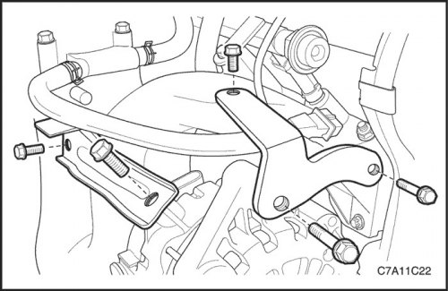
9. Remove the upper generator bracket.
10. Loosen the generator mounting bracket bolt to the intake manifold on the intake manifold and loosen the bolt on the generator.
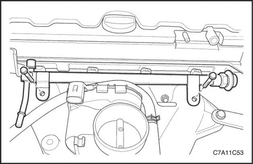
11. Remove the fuel rail assembly. See Section 1F2, Engine Controls - FAM II 2.4D.
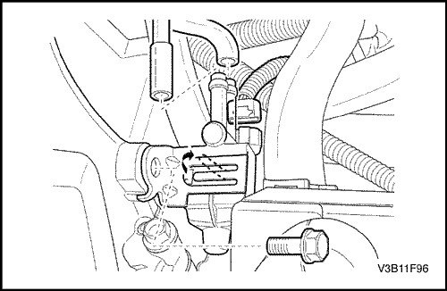
12. Remove the adsorber purge valve SUPB.See Section 1F2, Engine Controls - FAM II 2.4D.
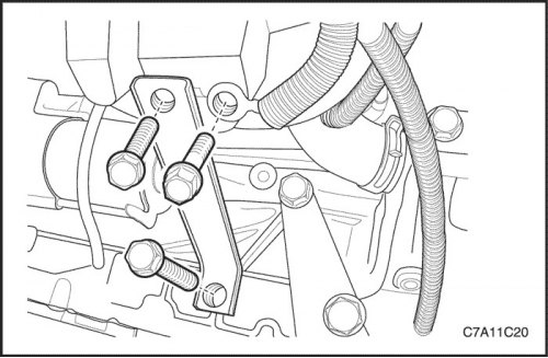
13. Remove the intake manifold support bracket bolt from the cylinder block and intake manifold.
14. Remove the intake manifold support bracket.
15. Loosen the ground terminal locking bolt.
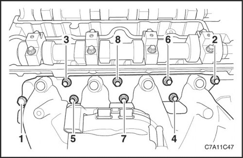
16. Remove the intake manifold retaining bolts and nuts in the following sequence.
17. Remove the intake manifold.
18. Remove the intake manifold gasket.
19. Clean the sealing surfaces of the intake manifold and cylinder head.
Installation procedure
1. Install a new intake manifold gasket.
2. Install the intake manifold.
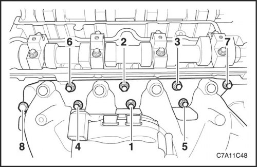
3. Install the intake manifold retaining bolts and nuts in the sequence shown below.
Tighten
Tighten the intake manifold retaining screws and nuts to 22 N·m (16 ft·lbs).
4. Tighten the ground wire terminal retaining bolt to the intake manifold.
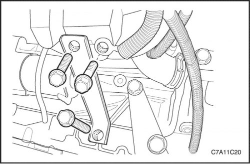
5. Install the intake manifold support bracket.
Tighten
Tighten the intake manifold support bracket bolts to the intake manifold and cylinder block to 25 N·m (18 ft·lbs).
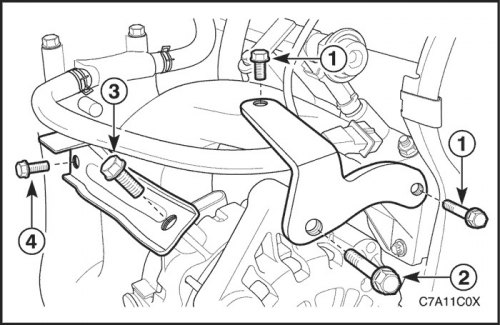
6. Install the upper generator bracket.
Tighten
Tighten the locking bolts (1) of the upper generator bracket to 25 Nm (18 ft·lbs), and bolt (2) with a torque of 35 Nm (26 ft·lbs).7.
7. Install the generator mounting bracket to the intake manifold.
Tighten
Tighten the locking bolt of the generator mounting bracket to the intake manifold (3) to a torque of 35 Nm (26 ft·lbs), and bolt (4) with a torque of 25 Н·м (18 ft·lbs).
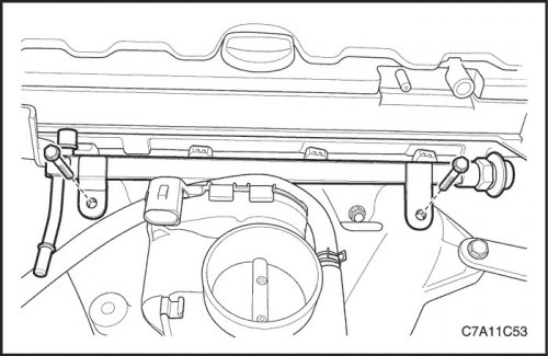
8. Install the fuel rail assembly. See Section 1F2, Engine Controls - FAM II 2.4D.
Tighten
Tighten the fuel rail assembly locking screws to 25 Nm (18 ft·lbs).
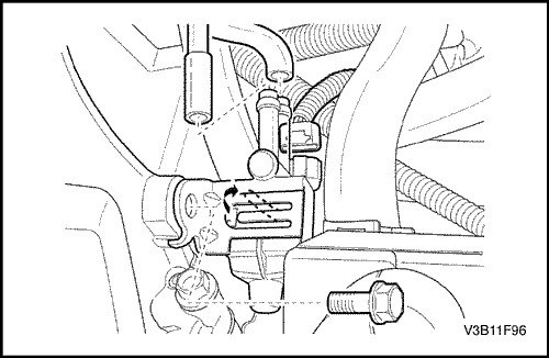
9. Install the purge valve of the SUPB adsorber.
Tighten
Tighten the purge solenoid valve support bracket bolt to 5 N·m (44 lbs.in).
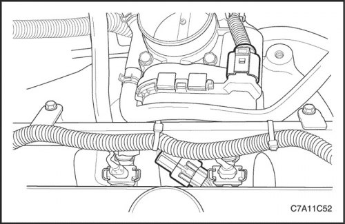
10. Reconnect all necessary vacuum lines that were previously disconnected.
11. Connect the MAP sensor connector.
12. Connect the electronic throttle control (ETC) sensor connector.
13. Connect the coolant hoses to the electronic throttle body.
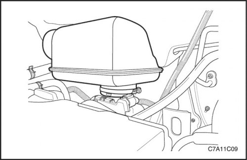
14. Connect the air cleaner outlet hose to the electronic throttle body connected to the resonator.
15. Connect the IAT sensor connector.
16. Connect the negative battery cable.
17. Fill the engine cooling system. See Section 1D2, Engine Cooling System - FAM II 2.4D.
Information taken from the official website: ChevyMan.ru