


Disassembly
Floating type piston pin
1. Remove the connecting rod cap and remove the connecting rod bearing shells.
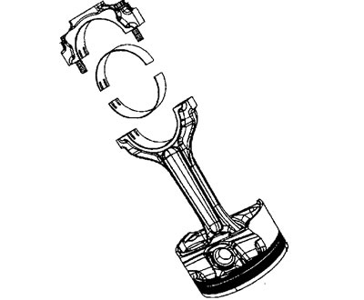
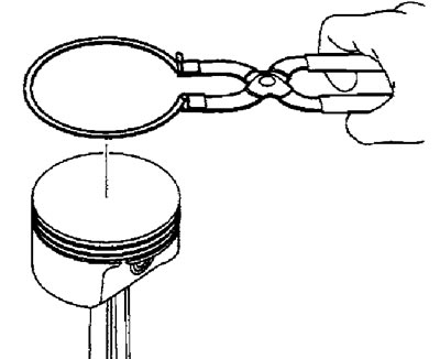
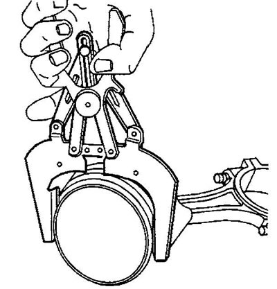
2. Using a piston ring puller, remove the rings.
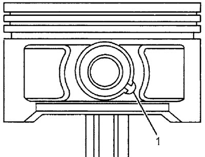
3. Turn the piston pin retaining ring so that the ends of the ring are in the recess (1) of the boss.
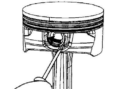
4. Using a screwdriver, remove the retaining ring.
5. Remove the piston pin, separate the piston and connecting rod.
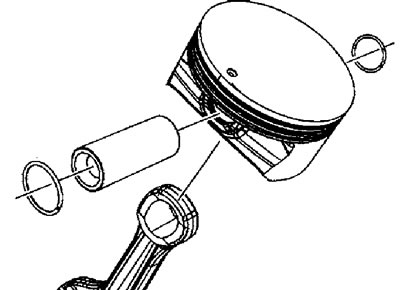
6. The combination of piston and piston pin is provided by selective assembly, replace the piston and pin only as a pair.
Press fit piston pin
Attention:
- Disassembling the piston, press-fit piston pin and connecting rod will usually damage the piston pin boss bores and piston pin. If the piston, pin and connecting rod have been separated, replace the entire assembly.
- The disassembly procedure given here should be used for diagnostic purposes only.
1. Remove the connecting rod bearing shells.
2. Remove the piston rings from the piston.
3. Install the piston and connecting rod into the disassembly fixture.
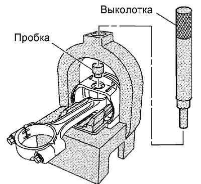
4. Install the plug into the piston pin.
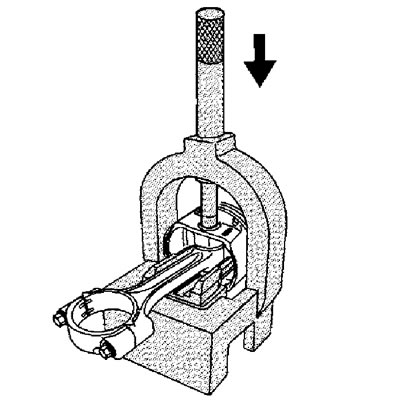
5. Install the drift through the fork of the device onto the piston pin plug
Note: The pressing pressure should not exceed 35,000 kPa to avoid damage to the device.
6. Press the piston pin out of the connecting rod and piston.
Wash and check
Attention:
- Replace pistons, pins and connecting rods that are damaged or show signs of excessive wear.
- The piston and piston pin are replaced as a pair.
- Do not clean the piston with a wire brush.
- Determination of the dimensions of the parts should be carried out at room temperature.
1. Remove varnish and carbon deposits from the piston (107) using a cleaning solvent. Wash all piston group parts with solvent.
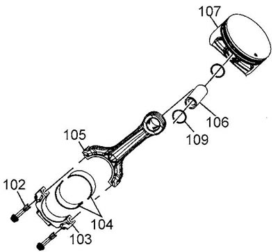
2. Dry the piston group parts with compressed air.
3. Clean the piston ring grooves with a special cleaning tool.
4. Clean the oil supply channels to the piston bosses and the oil drain holes in the oil scraper ring groove.
5. Inspect the piston, look for:
- Cracks in the piston ring comb, in the piston skirt and bosses.
- Nicks, burrs or distortion of piston ring grooves which may cause ring sticking.
- Minor defects can be removed with a fine file.
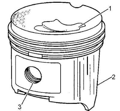
- Traces of gas erosion in the piston head (1).
- Piston skirt scoring or scratches (2).
- Scoring in the bore of the bosses for installing the piston pin (3).
6. Insert the edge of the piston ring into the piston ring groove. Roll the piston ring around the piston groove. If the resistance to movement of the ring is caused by distortion of the groove, remove the cause of the jam with a fine file. If the resistance to movement is caused by deformation of the piston ring, replace the ring.

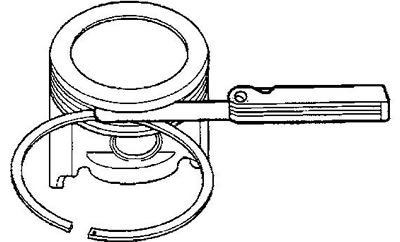
7. Measure the clearance between the piston groove and the ring using a flat feeler gauge. If the clearance is outside the permissible limits (see specification), try installing another piston ring. If the required clearance is still not achieved, replace the piston and piston pin.
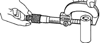
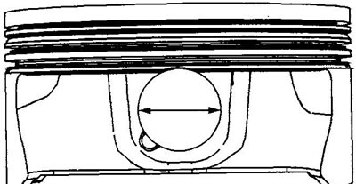
8. Measure the outer diameter of the piston pin and the inner diameter of the piston boss, determine the clearance between the piston and the piston pin. If the clearance is beyond the permissible limits (see specification), replace the piston and pin.
9. Measure the piston ring gap.
Warning:
- Do not file the ring to increase the clearance in the lock.
- Measure the clearance in the cylinder into which the ring will be installed.
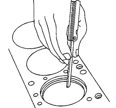
a) Install the piston ring into the cylinder approximately 6.5 mm below the ring stop at TDC. Orient the ring relative to the cylinder axis with the head of the inverted piston.
b) Measure the piston ring gap using a flat feeler gauge.
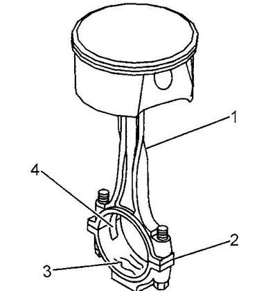
10. Inspect the connecting rod, look for:
- Signs of twisting of the connecting rod body (1).
- Signs of misalignment of the joint between the body and the connecting rod cap (2).
- Burrs or torn-out metal in the bearing bed (3).
- Signs of damage to the grooves (4) fixing the liners.
Warning:
- The connecting rod and connecting rod cap are machined together, do not mix up parts from different kits.
- The connecting rod and cover cannot be repaired; if defective, replace the connecting rod assembly.
- Do not attempt to repair the connecting rod threads for the cover mounting bolts.
11. Use measurements to determine the ovality of the connecting rod bearing bed, if the ovality is outside the tolerance range (see specification) replace the connecting rod.
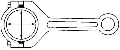
12. Measure the outside diameter of the piston pin and the inside diameter of the small end of the connecting rod to determine the clearance between the connecting rod and the piston pin. If the clearance is outside the permissible limits (see specification), replace the connecting rod or piston and pin.
13. Check the condition of the connecting rod bearing shells. See the section, "Checking the main bearing shells".
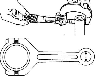
Measuring the outside diameter of the piston pin and the inside diameter of the small end of the connecting rod
Assembly
1. Install one piston pin retaining ring. Check that the ring is seated correctly in the boss groove.
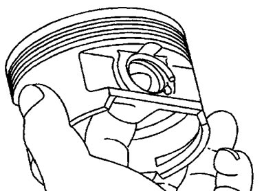
2. Assemble the piston and connecting rod. The mark (1) on the piston head and the projections (2) on the connecting rod should be on the same side.
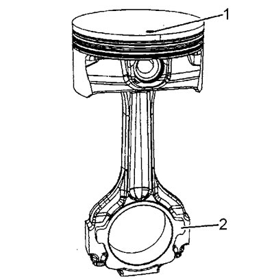
3. Install the piston pin into the piston and connecting rod.
4. Install the second piston pin retaining ring.
Caution: When installing piston rings, always use a piston ring puller. Spread the ring lock to the minimum amount necessary to install the ring.
5. Install the piston rings on the piston. Mark (point or part number) on the piston ring must be directed towards the piston head. If there is no mark on the upper compression ring, the ring can be installed in any direction.
6. Spread the oil scraper ring locks at least 25 mm apart.
7. Open the compression ring locks by 180°.
Note: The ring joints must not be located on the thrust side of the piston.
8. Install the connecting rod bearing shells into the connecting rod and cap.
[The article was borrowed from the website «ChevyMan»]