


Removal
Open the hood and disconnect the negative terminal from the battery.
Extract the refrigerant from the air conditioning system in accordance with the service equipment manual.
Remove the soundproofing screen, skid plate and engine splash guard.
Disconnect the wiring harness connector from the windshield washer motor.
Remove the washer reservoir and set it aside.
Loosen bolts 1 by 3-4 turns (figure 8-70) fastenings of the tension roller bracket, loosen the tension of the compressor drive belt by turning bolt 3 and remove belt 4 from the compressor pulley.
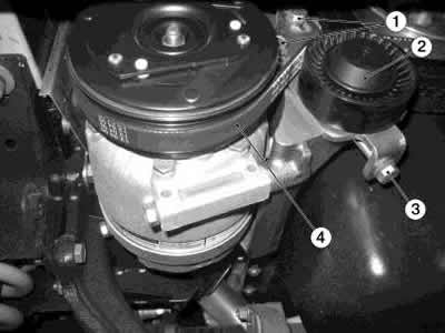
Figure 8-70. Compressor drive belt tensioner assembly:
1 - tension roller bracket mounting bolts;
2 - tension roller;
3 - tension mechanism bolt;
4 - compressor drive belt.
Disconnect the ignition system harness connector from the compressor connector.
Loosen bolt 3 (figure 8-71), remove compressor flange 4 and disconnect pipes 2 and 5 from the compressor.
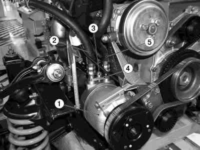
Figure 8-71. Fastening pipelines to the compressor:
1 - compressor;
2 - low pressure pipeline;
3 - compressor flange mounting bolt;
4 - compressor flange;
5 - injection pipeline.
Attention: install technological plugs on the hoses to prevent leakage of compressor oil.
Unscrew three bolts 1 (figure 8-72) fasten the compressor to the bracket and remove the compressor 4.
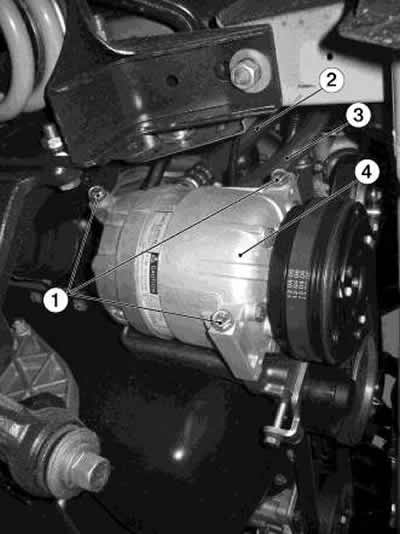
Figure 8-72. Removing the compressor:
1 - compressor mounting bolts;
2 - low pressure pipeline;
3 - injection pipeline;
4 - compressor.
Installation: Install the compressor on the engine bracket and secure with three bolts 1 (figure 8-72): bolt tightening torque — 20...24 Nm (2.0...2.4 kgf·m).
Remove the process plugs from the pipelines and install new sealing rings lubricated with compressor oil.
Install the pipelines and compressor flange onto the compressor and tighten the flange mounting bolt: bolt tightening torque: 50 Nm (5.0 kgf·m).
Install the drive belt onto the compressor pulley.
Attention: install the belt on the compressor pulley from the engine side.
Tension the belt by turning bolt 3, Figure 8-70, and tighten the tension roller mounting bolts. The bolt tightening torque is 20...24 Nm (2.0...2.4 kgf·m). The belt tension when measured on the upper branch should correspond to the value of the device for determining the oscillation frequency (173±3) Hz.
Connect the ignition system harness connector to the compressor connector.
Install the windshield washer reservoir and connect the ignition harness connector to the washer pump.
Install the engine splash guard, skid plate and sound insulation shield.
Connect the negative terminal to the battery.
Fill the air conditioning system with refrigerant according to the service equipment documentation.
Warning: It is strictly forbidden to refuel through a high-pressure pipeline (red service hose) with the engine running and the air conditioner on. To prevent damage to the filling equipment or injury, fill with the engine running and the air conditioner on only through the low-pressure line (blue service hose). All work with refrigerant must be performed wearing safety glasses.
[For details, visit the website CHEVYMAN.ru]