


To remove the heater, perform the following operations:
- drain the engine cooling system following the recommendations in the section "Removal and installation the engine";
- disconnect the ground cable from the battery;
- disconnect the electrical wires from the fan motor and resistor 10 (see figure 8-66);
- loosen clamps 10 (figure 8-65), disconnect the outlet and inlet hoses 9 of the radiator 1 of the heater from the engine cooling system pipes;
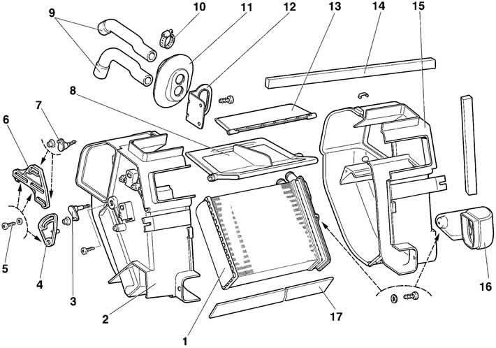
Figure 8-65. Heater parts:
1 - heater radiator;
2 - left heater casing;
3 - heater control flap control lever;
4 - intermediate lever;
5 - screw;
6 - sector of levers;
7 - air distributor flap drive lever;
8 - heater control flap;
9 - heater hoses;
10 - clamp;
11 - hose screen;
12 - bracket;
13 - air distribution flap;
14 - seal;
15 - right heater casing;
16 - passenger footwell heating air duct;
17 - radiator gasket.
- unscrew the two screws and remove the bracket 12 of the screen 11;
- remove the ventilation ducts 1, windshield heating 2, front 9 and rear 10 interior heating, driver and passenger foot heating 11;
- disconnect the valve drive rod 1 (figure 8-64), recirculation flap drive rod 4, heater control flap drive rod 11 from the heater and fan flaps;
- remove the water deflector shield, air filter 5 (see figure 8-57), housing 6 of the air intake filter and remove the fan assembly with the intermediate air duct 4;
- unscrew the two screws securing the intermediate housing 3 and the two screws securing the heater 15 to the instrument panel crossbar;
- unscrew the bolts securing the instrument panel crossbar to the steering wheel shaft bracket, to the side brackets and remove the crossbar;
- remove the heater assembly.
Remove the connecting brackets and disconnect the left 2 (see figure 8-65) and the right 15 heater casings. Unscrew the screws and remove the heater radiator 1.
Disconnect the intermediate air duct 1 (see figure 8-66) from the fan snail 9. Unscrew the screws and separate the left 4 and right 7 air intake housings.
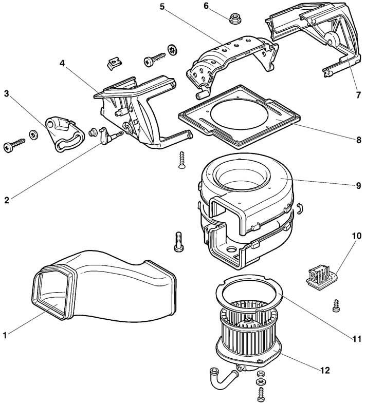
Figure 8-66. Disassembling the heater fan:
1 - intermediate air duct;
2 - recirculation flap drive lever;
3 - air intake flap lever;
4 - left air intake housing;
5 - recirculation flap;
6 - nut;
7 - right air intake housing;
8 - air intake shield;
9 - fan snail;
10 - additional resistor;
11 - Fan flange seal;
12 - heater electric fan.
Remove the brackets and separate the upper and lower parts of the fan coil.
Loosen the screws and remove the heater fan electric motor 12.
Install the heater in the reverse order. After installation and connecting the hoses, fill the engine cooling system with fluid and check the tightness of the connections.
The article is reprinted from the website: «CHEVYMAN.RU»