


- through the upper gaps of the instrument panel and the front door window blower nozzles, if you move the distribution lever to the extreme right position;
- through the side 16 (figure 8-63) and the central 8 nozzles, if the distribution lever is moved to the extreme left position;
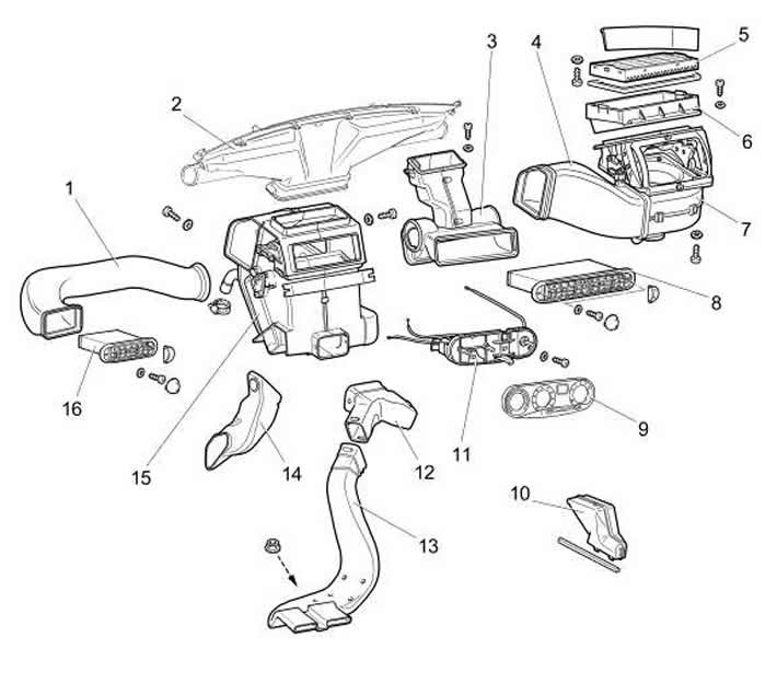
Figure 8-63. Interior heating system:
1 - ventilation air duct;
2 - windshield heating air duct;
3 - intermediate body;
4 - intermediate air duct;
5 - air filter;
6 - air intake filter housing;
7 - heating system fan;
8 - central ventilation nozzle;
9 - control lever trim;
10 - exhaust ventilation deflector;
11 - heater control levers;
12 - Front air duct for interior heating;
13 - rear air duct for interior heating;
14 - foot heating air duct;
15 - heater assembly;
16 - side nozzle.
- through the lower nozzles into the driver's and passenger's foot area if the distribution lever is in the middle position.
To increase the air supply to the car interior, turn on the electric fan 12 (see figure 8-66) heater switch 6 (figure 8-64).
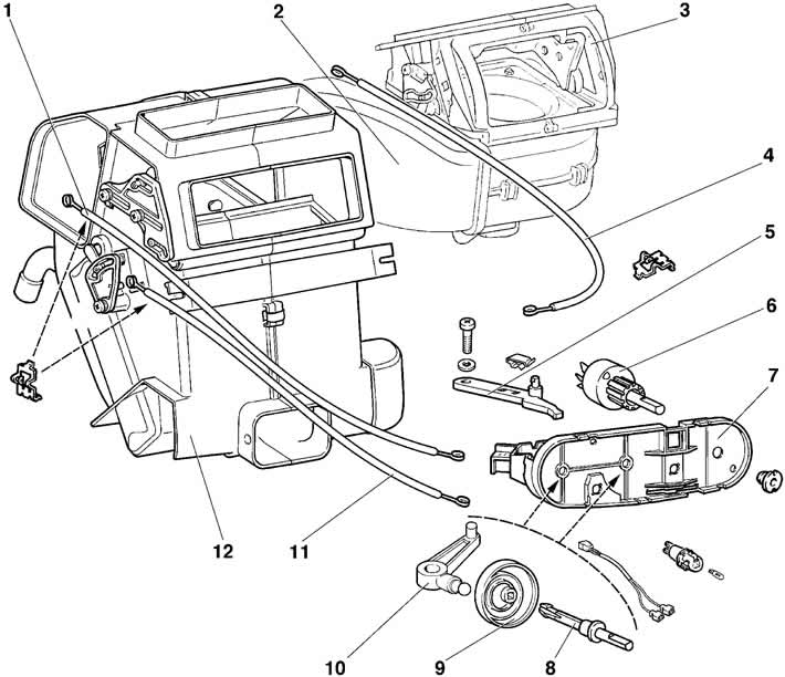
Figure 8-64. Heater flap control drive:
1 - valve timing drive rod;
2 - intermediate air duct;
3 - heater fan;
4 - recirculation flap drive rod;
5 - recirculation flap control lever;
6 - switch;
7 - control lever bracket;
8 - heater control flap drive shaft;
9 - lever drive cam;
10 - heater control lever.