


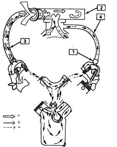
9.1. Air flow circulation diagram in the engine positive crankcase ventilation (PCV) system: 1 - PCV valve, 2 - air filter, 3 - crankcase outlet hose, 4 - PCV valve hose, a - Clean air, b - Crankcase gases, c - Air and gas mixture
2. The main components of the PVC system are the PCV valve, the filtered air intake hose and the vacuum hoses connecting these components to the engine and the EECS system.
3. To maintain idle speed, the PCV valve restricts flow when the intake manifold vacuum is high. In the event of abnormal operating conditions, the system design provides for the possibility of returning the breakthrough gases through the outlet pipe in the engine crankcase back to the air filter, from where they enter the engine and are consumed during fuel combustion.
4. Checking and replacing the forced ventilation valve and its filter is discussed in section 30 Chapter 1.