
Electronic ignition timing system (ESC) (for engines 1990-1992 release) or system with knock sensor (KS) (for engines produced since 1993).
Note. In 1993, the name of the electronic ignition control system (EST) has been changed. The system works as before, but is now referred to as a knock sensor system (KS).
3.1L engine
General description
1. The appearance of detonation in a running engine may be due to the unequal quality of fuel of different grades.
2. Electronic ignition control system (ESC) designed to change the ignition timing at angles up to 20°in order to eliminate detonation in the engine. This allows the engine to use the ignition advance to its maximum efficiency, which improves its performance and saves fuel.
3. No knock knock sensor system ESC (see illustration) sends a signal of 8-10 V to the ECM, after which the ECM ensures that the normal advance is set. When the sensor registers an increased level of vibration (when detonation occurs), the ESC turns off the circuit to the ECM control unit and the voltage on its contact "AT 7" drops to zero. The ECM then sends an ignition delay signal to the EST ignition distributor until detonation stops.
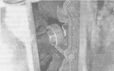
6.3. The knock sensor is located at the bottom of the engine compartment, closer to the passenger compartment
4. Signal failure from the knock sensor of the ESC system or wire break "masses" in the ESC will cause the signal voltage to the ECM to remain high. Under such conditions, the ECM will control the EST system as if there was no detonation. Therefore, the distributor will not set the ignition delay and when the engine is under heavy load, the level of detonation can become very high. Then the ECM will issue code 43.
5. If there is no signal from the ESC system to the ECM, the latter will continuously send a signal to the EST to set the ignition delay. As a result, the engine throttle response will slow down and the ECM will issue a code 43.
Examination
6. The sequence of checking the ESC system is shown in the diagram (see diagram).

{{Открыть большую картинку в новом окне}} »
6.6. ESC System Test Sequence Diagram (or KS) on 3.1 l engine
This circuit should only be used after checking all other possible factors contributing to knocking, such as ignition timing, EGR system (EGR), engine temperature, excessive engine noise, etc.
Replacing elements
ESC knock sensor
7. Disconnect a wire from a negative conclusion of the storage battery.
8. Pull off the insulating tube from the sensor and disconnect the electrical connector from it.
9. Remove the knock sensor from the cylinder block.
10. The sensor is installed in the reverse order.
ESC block
11. Disconnect a wire from a negative conclusion of the storage battery.
12. Remove the glove box (see chapter 11, section 26).
13. Locate the unit mounted on the ECM bracket behind the glove box.
14. Disconnect from the block a socket.
15. Having turned away bolts, remove the block from the car.
16. The block is installed in the reverse order.
3.8L engine
General description
17. The ESC system in this engine consists of a knock sensor and a PCM. The engine-mounted MEM-CAL unit has the same functions as the ESC units found on other engine models. All diagnostic procedures for checking this system should be carried out in a service center or in a specialized repair shop.