
Air conditioning compressor clutch control
Note: To determine the relay installation locations, refer to Figures 6.2a and 6.2b section 6 Chapter 12.
44. During operation of the air conditioning system, the system compressor clutch is switched on and off by commands from the ECM/PCM unit. The ECM/PCM unit controls the operation of the air conditioning system compressor clutch relay, delaying the clutch engagement moment by approximately 8 seconds (on 3.1 l engines) or 0.4 seconds (on 3.8 l engines) after the air conditioning system is turned on: this allows the IAC valve to regulate the idle speed to take into account the additional load. In addition, the ECM/PCM unit, via the same relay, disengages the clutch in engine operating modes with the throttle valve fully open to avoid excessively high compressor rotation speed.
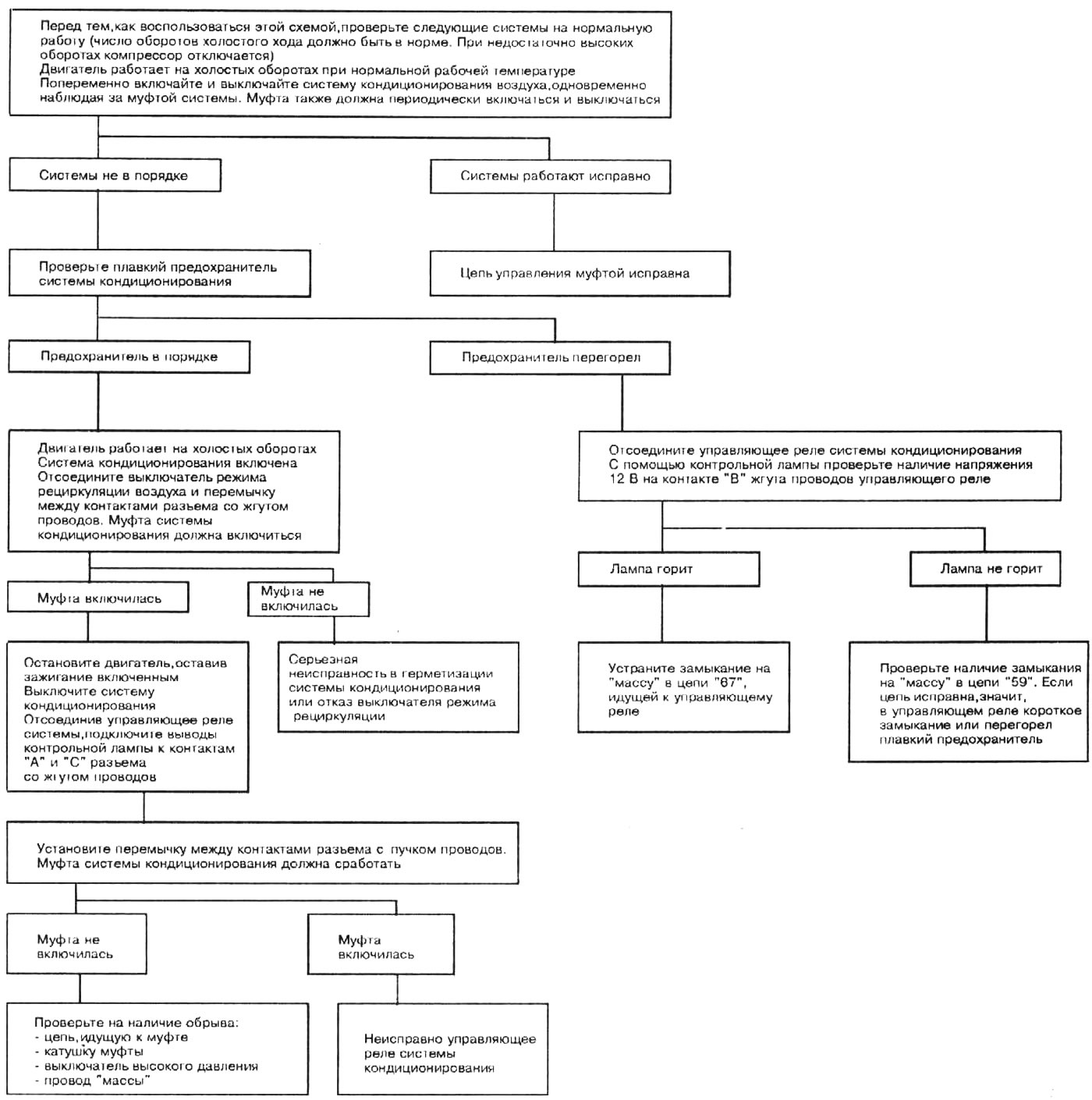
45. The attached diagnostic diagram shows the sequence of operations for checking the compressor clutch control (see illustration).
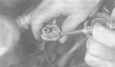
4.45a. Using a test lamp, check if the pink/white wire going to the electrical connector of the air conditioning control relay is at 12 V
Open large image in new tab →
4.45b. Sequence diagram of checking the control mechanism of the air conditioning system clutch
"Turn on air conditioning" signal (pressing a button in the cabin)
46. When a signal is given to turn on the air conditioning system, voltage from the battery is supplied to the compressor clutch and to terminal "B8" (on a 3.1 l engine) or "BD11" (on a 3.8 l engine) eCM/PCM electrical connector via circuit "67" (blue wire going to the pressure switch) (see illustration 4.45c), as a result, the air consumption at idle speed increases, which ensures that the required idle speed is maintained.
47. In most cases, the cause of the air conditioning system failure is not the ECM/PCM unit, but the control relay and switches of this system.
48. If the air conditioning system operates normally, but the idle speed when the system compressor is turned on is very low or, conversely, too high when it is turned off, check for breaks in the circuit section (dark green with white wire) between the air conditioning control relay and the ECM/PCM to the ECM/PCM (see illustration 4.45c or 4.45d). If this section of the circuit is not damaged, the fault should be sought in contact "B8" (for 3.1L engine), "BD11" (for 3.8L engine) eCM/PCM unit or in the ECM/PCM unit itself.
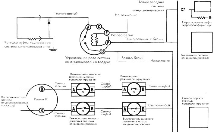
4.45v. Electrical circuit diagram with control relay of air conditioning system of cars with 3.1 l engine
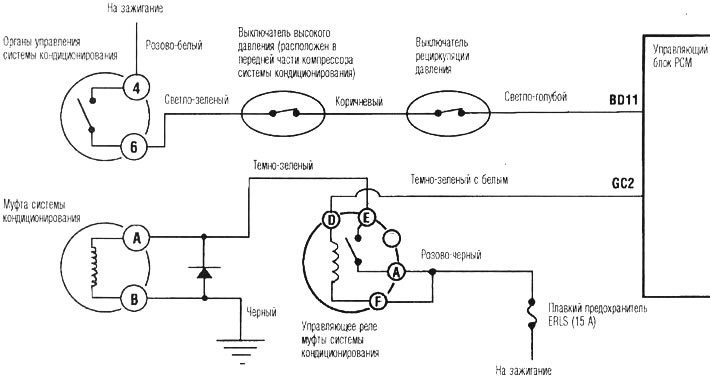
4.45g. Electrical circuit diagram with control relay of air conditioning system of cars with 3.8 l engine