
Contents: General description ↧ Examination ↧
General description
6. MAP sensor (see illustration) carries out current monitoring of pressure changes in the manifold, which are associated with changes in load and engine crankshaft speed, and converts this information into output voltage. The ECM uses the MAP sensor to control fuel delivery and ignition timing.
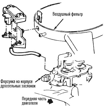
4.6. MAP sensor assembly parts for 3.1L engine
7. A failure in the CLAR sensor circuit should result in a code 33 or code 34 being set.
Examination
8. The MAP sensor testing procedures are provided in the attached diagnostic chart (see block diagram).
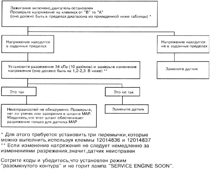
4.8a. Diagnostic chart for checking the MAP output signal
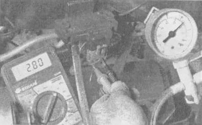
4.8b. Apply vacuum to the MAP sensor and read the voltage value. Connect the positive lead to the signal wire (terminal "B") and the negative lead to ground (terminal "A"). The voltage should decrease
| Height | Voltage range | |
| Meters | Feet | Volts |
| Below 305 | Below 1000 | 3,8-5,5 |
| 305-610 | 1000-2000 | 3,6-5,3 |
| 610-914 | 2000-3000 | 3,5-5,1 |
| 914-1219 | 3000-4000 | 3,3-5,0 |
| 1219-1524 | 4000-5000 | 3,2-4,8 |
| 1524-1829 | 5000-6000 | 3,0-4,6 |
| 1829-2133 | 6000-7000 | 2,9-4,5 |
| 2133-2438 | 7000-8000 | 2,8-4,3 |
| 2438-2743 | 8000-9000 | 2,6-4,2 |
| 2743-3048 | 9000-10000 | 2,5-4,0 |
| Low altitude = High pressure = High voltage | ||
The original material is located on the website: «CHEVYMAN.RU»