


Two types of computers are used. Cars with 3.1L engine are equipped with ECM with EPROM (programmable read-only memory - PROM) and a CALPAK unit. Cars with a 3.8 L engine are equipped with a PCM with a MEM-CAL unit.
Note: The CALPAK unit on 3.1L engines is not replaceable. If the CALPAK unit fails, the entire ECM unit must be replaced.
The ECM/PCM unit controls the following parameters and processes:
- Fuel consumption
- Ignition distribution (setting the lead angle)
- Ignition control
- Exhaust gas recirculation
- Operation of the air intake
- Engine fan
- Idle Air Consumption (IAC)
- Torque converter
- Air conditioning control system
The work of the CCC system is similar to the work of the central nervous system in the human body. Sensors (nerve endings) constantly send information to the ECM/PCM unit (brain), which processes the data and, if necessary, sends commands to change the operating parameters of the engine (body).
Let's give an example of how one of the parts of the system works. The oxygen sensor, located in the exhaust manifold, monitors the oxygen content in the exhaust gases. If the oxygen content in the exhaust gases deviates from the norm, an electrical signal is sent to the ECM/PCM. The ECM/PCM receives this information, processes it and sends a command to the fuel injection system to change the fuel/air mixture ratio. This is done in a fraction of a second and is done continuously while the engine is running. The end result is constant maintenance of the required fuel/air mixture ratio, regardless of external conditions.
Some may find that a system equipped with an on-board computer and electrical sensors is difficult to test. This is not at all necessary. The SSS system includes a built-in diagnostic mode that indicates the presence of a malfunction by lighting a lamp "SERVICE ENGINE SOON" ("Service the engine immediately") on the instrument panel. If this lamp illuminates during normal engine operation, it means that a fault has been detected in one of the information sensors or in the ECM/PCM itself. More importantly, a fault code is stored in the ECM/PCM memory.
To retrieve this information from the ECM/PCM memory, a short jumper wire must be used to ground the diagnostic terminal. This terminal is part of the ALDL central connector (see illustration). ALDL is located under the instrument panel and to the left of the center console. To use ALDL, remove the plastic cover (if it is installed), pushing it towards himself. Having opened the connector in this way, insert one end of the jumper into the diagnostic terminal and press the other end to the ground.
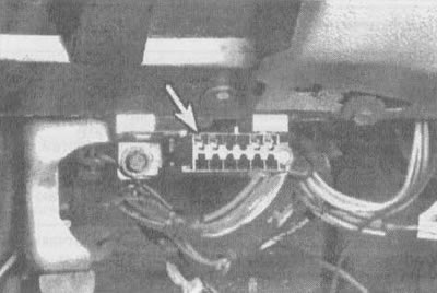
2.6a. Central connector (ALDL) (shown by arrow) located under the dashboard next to the fuse box |
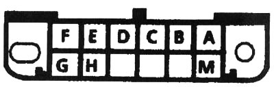
2.6b. Description of terminals on the central ALDL connector: A - "ground", B - diagnostic terminal, C - AIR (if used), D - lamp "SERVICE ENGINE SOON" ("Urgent engine maintenance"), E-sequential data (do not use - special device required), F -TCS (if used), G - fuel pump (if used), M - serial data (if used) |
When the diagnostic terminal is connected to ground, the ignition is on and the engine is stopped, the system will enter diagnostic mode.
Caution! Do not start or crank the engine with the diagnostic terminal connected to ground. In this mode, the ECM/PCM will display code 12 by flashing the lamp "SERVICE ENGINE SOON", indicating that the system is working. Code 12 corresponds to one flash, followed by two flashes in a row after a short pause. This code will flash three times. If no other codes are stored in memory, code 12 will continue to be displayed until the diagnostic terminal is grounded.
After code 12 has flashed three times, the ECM/PCM will display any of the stored fault codes. Each such code will illuminate three times, then code 12 will illuminate again, indicating that the display of the stored fault code is complete.
When the ECM/PCM sets a DTC, the lamp illuminates "SERVICE ENGINE SOON", and the fault code is written into memory. If the malfunction is temporary, then when it disappears after 10 seconds the lamp will go out. However, the DTC will remain stored in the ECM/PCM memory until the battery voltage to the ECM/PCM is disconnected. Disconnecting the battery for 10 seconds will clear all stored fault codes. Fault codes should always be cleared after repair work is completed.
Caution: To prevent damage to the ECM/PCM, the ignition switch must be in the "OFF" position when power is applied or disconnected to the ECM/PCM.
Above is a list of common fault codes that may be encountered when testing the computer command control system. Simplified troubleshooting operations are also included. If these steps do not resolve the problem, you should contact a car repair shop.
| Error code | Chain or system | Possible cause |
| Code 12 (1 flash, pause, 2 flashes) | No pulses are sent from the distributor to the ECM/PCM unit | This code will always be displayed when the diagnostic terminal is connected to ground with the ignition on and the engine not running. If additional fault codes are stored in the ECM/PCM memory, they will appear after this code has been repeated three times. If this code appears when the engine is running, it means that the pulses from the distributor are not reaching the ECM/PCM |
| Code 13 (1 flash, pause, 3 flashes) | Oxygen sensor circuit | The throttle position sensor may be stuck or incorrectly adjusted. Check the wires and connectors associated with the oxygen sensor. Replace the oxygen sensor |
| Code 14 (1 flash, pause, 4 flashes) | Coolant sensor (high temperature) | If any faults occur in the cooling system, they must be corrected immediately. Check all wires and connectors associated with the coolant temperature sensor. Replace the coolant temperature sensor * |
| Code 15(1 flash, pause, 5 flashes) | Coolant sensor (low temperature) | See above, then check all electrical connections to the ECM |
| Code 16 (only for 3.8L engine) (1 flash, pause, 6 flashes) | Voltage in the system (high or low) | System voltage detected to be above 17V or below 9V |
| Code 18 (only for 3.8L engine) (1 flash, pause, 8 flashes) | Misaligned camshaft/crankshaft position | Temporary malfunction associated with the camshaft/crankshaft signal or fuel supply signal |
| Code 21 (2 flashes, pause, 1 flash) | Throttle Position Sensor TPS (high voltage) | Possible TPS sticking or improper adjustment (throttle position sensor). Check the wires and connectors between the TPS and the ECM/PCM. Adjust or replace the TPS sensor (see chapter 4) * |
| Code 22 (2 flashes, pause, 2 flashes) | Throttle Position Sensor TPS (low voltage) | Check TPS adjustment (Chapter 4). Check ECM/PCM connector. Replace TPS (Chapter 4) * |
| Code 24 (2 flashes, pause, 4 flashes) | Vehicle speed sensor | An error in this circuit should only be displayed when the vehicle is moving. Ignore code 24 if the drive wheels do not turn. Check connections at ECM. Check TPS settings |
| Code 26 (only for 3.8L engine) (2 flashes, pause, 6 flashes) | QDM Error "A" | The PCM registers an incorrect voltage level in the circuit connected to the QDM (quadruple master block) "A" |
| Code 32 (only for 3.1L engine) (3 flashes, pause, 2 flashes) | Exhaust Gas Recirculation (EGR) System | Vacuum switch shorted at cranking, switch does not close circuit after EGR is commanded by ECM for a certain period of time, or EGR solenoid circuit is open for a certain period of time. Replace EGR valve * |
| Code 33 (only for 3.1L engine) (3 flashes, pause, 3 flashes) | MAP sensor | Check the vacuum hoses coming from the MAP sensor. Check the electrical connections at the ECM. Replace the MAP sensor * |
| Code 34 (only for 3.1L engine) (3 flashes, pause, 4 flashes) | Vacuum sensor or MAP sensor | Code 34 will be set when the MAP sensor signal voltage is too low. The ECM will replace this signal with a fixed MAP value and use the TPS to control fuel delivery. Replace MAP sensor * |
| Code 34 (only for 3.8L engine) (3 flashes, pause, 4 flashes) | MAF sensor | Code 34 will be set when the signal voltage from the MAF sensor is absent for a period exceeding 4 seconds |
| Code 41 (only for 3.8L engine) (4 flashes, pause, 1 flash) | Camshaft Sensor Circuit | Code 41 will be set when the signal voltage from the camshaft sensor is absent for a period exceeding 5 seconds |
| Code 42 (4 flashes, pause, 2 flashes) | Electronic Spark Plug Distribution (EST) | Electronic ignition timing bypass circuit or EST circuit is shorted or open (EST). This code may be caused by a faulty HEI module |
| Code 43 (4 flashes, pause, 3 flashes) | Electronic ignition control (ESC) | The ESC delay signal was on for too long or the system failed the ESC unit functional test |
| Code 44 (4 flashes, pause, 4 flashes) | Oxygen sensor indicates lean exhaust | Check the ECM electrical connections, especially terminals "15" and "8". Check the TBI base gasket, vacuum hoses and intake manifold gasket for leaks. Replace the oxygen sensor * |
| Code 45 (4 flashes, pause, 5 flashes) | Oxygen sensor indicates rich exhaust | Possible faulty or leaking injector, high fuel pressure or faulty TPS and MAF sensors. Also check for gasoline contamination of the charcoal fuel vapor canister and its components. Replace the oxygen sensor * |
| Code 51 (5 flashes, pause, 1 flash) | EPROM (3.1L engine) or MEM-CAL (3.8L engine) | Make sure the EPROM or MEM-CAL is installed correctly in the ECM. Replace the EPROM or MEM-CAL * |
| Code 52 (only for 3.1L engine) (5 flashes, pause, 2 flashes) | CALPAK | Make sure the ECM is installed correctly. Replace the ECM * |
| Code 54 (only for 3.1L engine) (5 flashes, pause, 4 flashes) | Fuel pump | Fuel pump low voltage. Set when the voltage at the fuel pump is less than 2 V and when reference pulses are received |
| Code 55 (5 flashes, pause, 5 flashes) | ECM/RSM | Make sure the ECM ground connections are tight. If so, replace the ECM/PCM * |
| Code 56 (only for 3.8L engine) (5 flashes, pause, 6 flashes) | QDM Error "B" | The PCM registers an incorrect voltage level in the circuit connected to the QDM (quadruple master block) "IN" |
* Replacing a system element may not always resolve the problem. In this regard, before purchasing spare parts, consult a specialist.
Note: On 3.8L engines there are several codes that are not displayed by the light "SERVICE ENGINE SOON" on the dashboard. A special device is required to read these codes \(gM Tech 1 Scanning Device).