
General description
1. To ensure high driving performance of the car in various climatic conditions, it is equipped with an intake air heating system. With a constant temperature of the air entering the engine, it becomes possible to more accurately adjust the fuel supply system and thereby reduce the level of emission of combustion products into the atmosphere, as well as eliminate the possibility of icing of the throttle valve.
2. THERMAC air filter thermostat (see illustration) is driven by heated air and vacuum created in the collector. Air can enter the filter both from the exhaust manifold area and through the air intake in front of the radiator. The operating mode of the THERMAC thermostat is set based on the readings of the temperature sensor located in the filter housing.
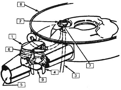
10.2. THERMAC Air Filter Device: 1 - vacuum diaphragm, 2 - temperature sensor, 3 - vacuum hose (manifold suction hose), 4 - heated air intake, 5 - air intake, 6 - linkage, 7 - air outlet valve, 8 - air cleaner assembly, 9 - damper
Examination
3. Possible causes of interruptions in the operation of the engine during its warm-up:
- A) The heated air pipe is disconnected.
- b) The vacuum diaphragm does not work.
- V) No vacuum is created in the manifold.
- G) Thermostat flap does not move. /
- d) Missing adapter seal between air filter housing and TBI unit.
- e) The air filter cover seal is missing.
- and) Loose air filter cover.
- h) Loose air filter housing.
4. The reasons for the lack of engine power and slow acceleration can be:
- A) Stuck thermostat damper that does not open to take in outside air.
- b) The temperature sensor does not release vacuum.
5. Check the condition of the system and make sure all hoses and heated air intake are properly connected. Check for kinked, clogged or worn hoses.
6. Check the presence and condition of the gasket between the air filter and the injector housing or intake manifold.
7. With the air filter installed, the thermostat damper must be open to outside air.
8. Start the engine. Watch the behavior of the thermostat valve. When the engine is started for the first time, the damper should move and block the intake of outside air. As the engine warms up, the thermostat valve should open slowly.
9. If the thermostat does not operate as described above, the damper may not move when the engine reaches the correct temperature. If you experience problems with engine response during engine warm-up, check the condition of the temperature sensor by performing the following test.
10. With the engine off, disconnect the hose from the vacuum diaphragm motor.
11. Apply a vacuum of at least seven inches to the vacuum diaphragm (18 cm). When creating such a vacuum, the muffler damper must completely block the intake of outside air. If this does not happen, check the correct operation of the drive linkage.
12. After creating a vacuum, try to keep it in the vacuum diaphragm motor by pinching the hose. The muffler damper must remain closed. If it opens, replace the vacuum diaphragm. A stuck linkage or corroded air intake is more likely to cause damage to the vacuum diaphragm than to damage to the diaphragm itself. Therefore, do not rush to change the aperture without checking these two nodes.
13. If checking the vacuum diaphragm shows that it is working, check the condition of the vacuum hoses and the reliability of their connections. If they are OK, replace the temperature sensor.
14. Start testing when the air cleaner temperature is below 30°C. If the engine has been running recently, remove the air filter cover and place the thermometer as close to the sensor as possible. Let the engine cool down until the thermometer shows 30°C for 5-10 minutes. Replace the filter cover.
15. Start the engine at idle. When the engine has cooled down sufficiently, the thermostat valve should immediately move and shut off the outside air. When the damper begins to open after a few minutes, remove the air filter cover and measure the temperature. It should be approximately 55°C.
16. If the thermostat valve does not open at the specified temperature, the temperature sensor is defective and should be replaced.
Replacing elements
Vacuum diaphragm
17. Remove the air filter cover (see chapter 4, section 8).
18. Disconnect the vacuum tube (see illustration).
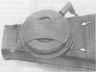
10.18. After removing the air filter cover from the TBI unit, turn it over and disconnect the vacuum line from the temperature sensor, ream the two spot welds (shown by arrows) drill with a diameter of 1.6 mm; if necessary, expand them and remove the band clamp
19. Drill out two spot welds with a 1/16" drill (1.6 mm), then enlarge the holes just enough to allow the band tie to be removed. Be careful not to damage the air intake.
20. Bend the clamp to the side.
21. Remove the diaphragm by tilting it to the side to disengage the linkage.
22. To install a new diaphragm, drill a 7/64" hole in the air intake (2.8 mm) in such a way that it passes through the center of the clamp that fixes the vacuum diaphragm.
23. Install the vacuum diaphragm linkage to the thermostat valve.
24. Install the diaphragm on the air intake, securing the clamp holding it with a special screw included in the engine parts kit. Make sure the screw does not interfere with the operation of the assembly. Shorten the screw if necessary.
25. Install the air filter cover (see chapter 4, section 8). Connect the vacuum hose to the diaphragm.
Sensor
26. Remove the air filter cover (see chapter 4, section 8).
27. Note the position of the sensor (see illustration); this will help you when assembling the node.
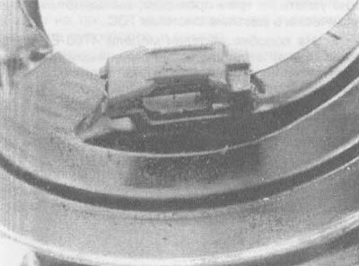
10.27. Mark the position of the sensor
28. Using a suitable tool, bend the tabs of the sensor clamp (see illustration). Remove the clamping bracket together with the sensor.
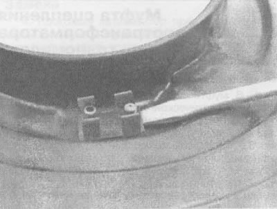
10.28. Using a small screwdriver, pry up the tabs on the sensor clamp
29. The sensor is installed in the reverse order. Upon completion, attach two vacuum pipelines to the sensor nozzles.