
General description
1. This system is designed to capture and accumulate fuel vapors evaporating from the gas tank, throttle body and intake manifold.
2. The Evaporative Emission Control System (EECS) consists of a canister filled with activated carbon and lines connecting this canister to the fuel tank and manifold, a valve and vacuum tubes (see illustration).
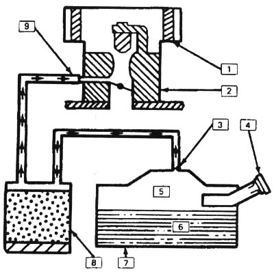
8.2. Fuel vapor control system installed on the 3.1 L engine: 1 - air jet, 2 - TV! block, 3 - jet, 4 - pressure/vacuum release cover, 5 - fuel vapor, 6 - fuel, 7 - fuel tank, 8 - reservoir, 9 - valve
3. Fuel vapors are transferred from the fuel tank, throttle body and intake manifold to the canister where they accumulate while the engine is not running. When the engine starts running, fuel vapors are carried out of the tank by the air flow and burn along with the fuel.
Examination
4. If the engine idles poorly, stalls, and has poor throttle response, this may be due to a faulty valve, a damaged reservoir, or cracked or improperly connected hoses.
5. Leaks or a strong smell of gasoline may be caused by: leaks in the fuel lines or TBI unit, damage to the tank, faulty drain valve, damage to the valve, disconnection, improper connection, excessive kinking, wear or damage to the ventilation or vapor control system hoses, or improper installation of the air cleaner or its gasket.
6. Check all hoses connected to the tank for kinks, leaks and breaks along their entire length. If necessary, repair any damage or replace any faulty components.
7. Check the condition of the tank. If it is cracked or otherwise damaged, replace the tank.
8. Check for leaks at the bottom of the tank. If there is a fuel leak, replace the tank and check the technical condition of the hoses and their correct routing.
9. Place a short piece of hose on the lower valve port and try to blow through it. Very little or no air should pass into the tank (the small amount of air that gets in is explained by the fact that the tank has a constantly open ventilation hole).
10. Using a hand vacuum pump, create a vacuum in the area between the control valve tube and its diaphragm.
11. If the diaphragm holds the vacuum for less than 20 seconds, it means that it is leaking air and the tank should be replaced with a new one.
12. If the diaphragm holds the vacuum well, try blowing out the hose again while there is still vacuum in the system. This time the air flow should increase noticeably. If this does not happen, replace the tank.
Replacement of elements
13. Disconnect all vacuum lines from the reservoir (see illustration), having previously applied clearly visible marks to them.
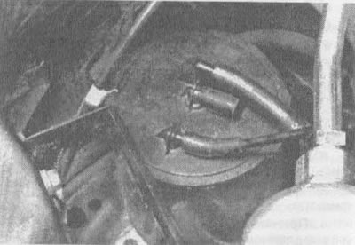
8.13. To remove the tank, mark and disconnect the vacuum tubes from it, then unscrew the tank clamp bolt and remove the tank
14. Loosen the clamp bolt and remove the tank.
15. Installation is carried out in reverse order.