


Contents: Installing the primary and secondary… ↧ Installing the secondary timing… ↧ Removal procedure ↧ Camshaft primary drive chain ↧ Secondary timing chain for… ↧ Clear, clean ↧ Inspection ↧ Installation procedure ↧
Important! Setting the valve timing is required in all cases where the camshaft drive system has been affected and the required relationship between any chain and sprocket has been disrupted. Even if this applies to only one sprocket, repeated crankshaft rotations will not reproduce conditions in which the correct valve timing can be maintained. To set the valve timing, if required, follow the instructions for installing the secondary camshaft drive chain for bank 2.
Installing the primary and secondary drive chains of the camshafts of cylinder bank 2
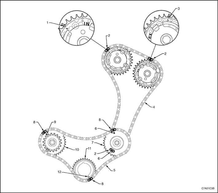
1. Installation mark of the intake camshaft timing control drive, row 2
2. Shiny Secondary Timing Chain Link Bank 2
3. Timing mark for variable valve timing drive, exhaust camshaft, row 2
4. Secondary Timing Chain, Bank 2
5. Primary timing chain
6. Timing mark for intermediate camshaft sprocket, row 2
7. Intermediate camshaft sprocket, row 2
8. Shiny primary timing chain link
9. Timing mark for intermediate camshaft sprocket, row 2
10. Intermediate camshaft sprocket, row 1
11. Crankshaft sprocket
12. Crankshaft sprocket timing mark
Installing the secondary timing chain for cylinder bank 1
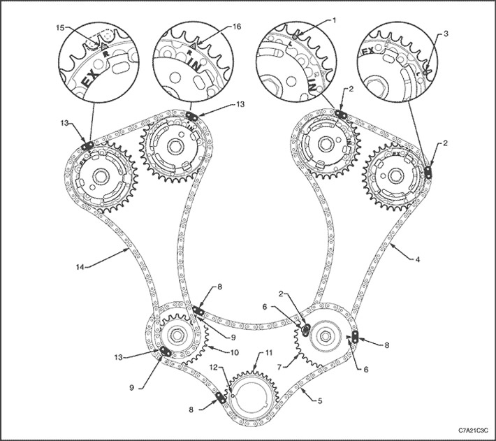
1. Installation mark of the intake camshaft timing control drive, row 2
2. Shiny Secondary Timing Chain Link Bank 2
3. Timing mark for variable valve timing drive, exhaust camshaft, row 2
4. Secondary Timing Chain, Bank 2
5. Primary timing chain
6. Timing mark for intermediate camshaft sprocket, row 2
7. Primary drive sprocket intermediate shaft camshaft drive, row 2
8. Shiny primary timing chain link
9. Timing mark for intermediate camshaft sprocket, row 2
10. Intermediate camshaft sprocket, row 1
11. Crankshaft sprocket
12. Crankshaft sprocket timing mark
13. Shiny Secondary Timing Chain Link Bank 1
14. Intermediate timing chain, bank 1
15. Timing mark for variable valve timing drive, exhaust camshaft, row 1
16. Installation mark of the intake camshaft timing control drive, row 1
Removal procedure
Secondary timing chain for camshafts, cylinder bank 1
Caution: After removing the upper intake manifold and spark plugs, it is necessary to seal all openings to prevent dirt and foreign substances from getting inside.
1. Remove the front engine cover assembly. See "Front cover assembly" in this section.
2. Remove the spark plugs to make it easier to turn the crankshaft or engine.
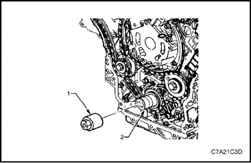
3. Install the EN-46111 tool (1) on the crankshaft (2).
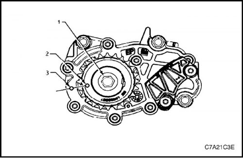
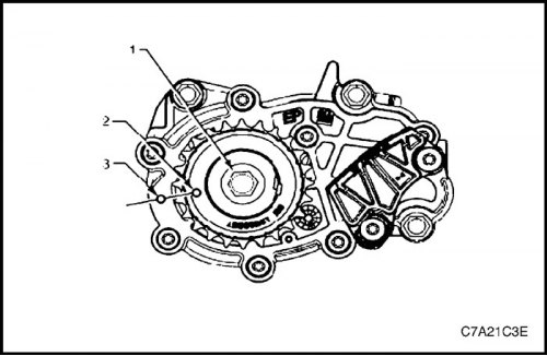
4. Using the EN-46111 tool (1), turn the crankshaft clockwise until the timing mark (2) on the crankshaft sprocket is aligned with the mark (3) on the oil pump housing.
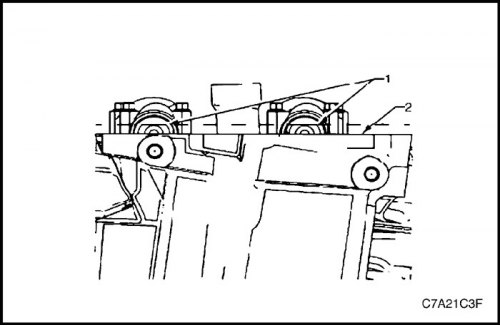
5. After aligning the marks, check whether the chamfers (1) of the camshafts at the rear end of the cylinder head of row 1 are parallel to the joint surface (2) with the cylinder head cover.
6. If the camshaft flats are not positioned as shown, the crankshaft should be rotated 360°.
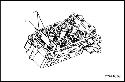
7. Fit the EN 46105-1 tool (1) to the rear ends of the camshafts (2) of cylinder bank 1.
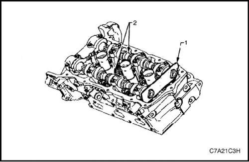
8. Fit the EN 46105-2 tool (1) to the rear ends of the camshafts (2) of cylinder bank 2.
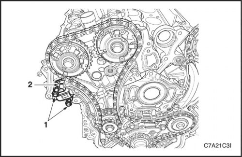
9. Remove the bolts (1) of the secondary timing chain tensioner for cylinder bank 1 and remove the tensioner (2).
Note: Use caution when removing the tensioner bolts. The tensioner plunger may spring back and pop out when the tensioner is removed.
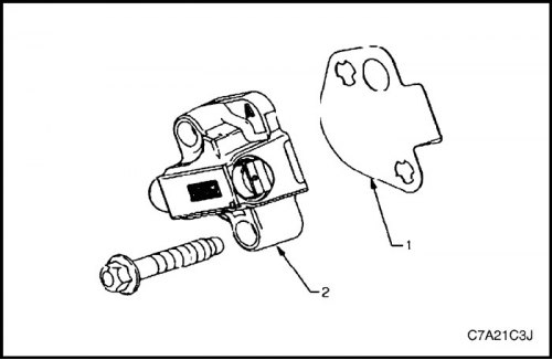
10. Remove the gasket (1) from the tensioner (2) and discard it.
11. Inspect the tensioner mounting surface on the bank 1 cylinder head for any burrs that may affect the seal of the new tensioner gasket.
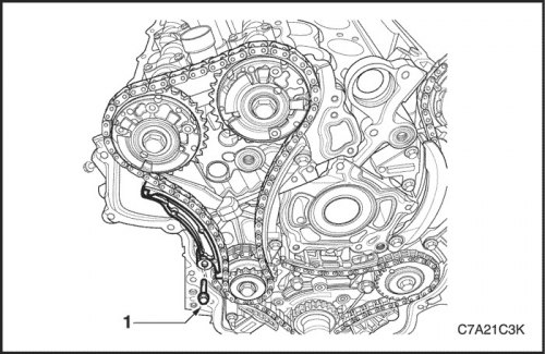
12. Remove the bolt (1) of the secondary timing chain shoe for cylinder bank 1.
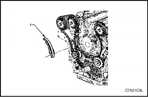
13. Remove the shoe (1) of the secondary drive chain of the camshafts of cylinder bank 1.
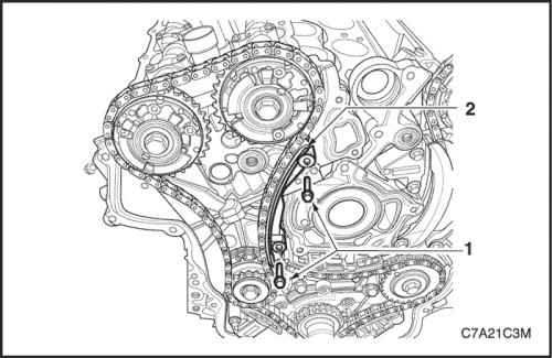
14. Remove the two bolts (1) of the secondary timing chain guide for cylinder bank 1 and remove the guide (2).
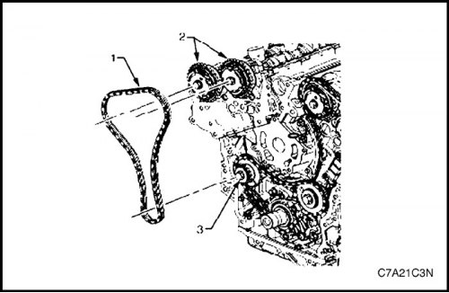
15. Remove the chain (1) of the secondary drive of the camshafts of cylinder bank 1 from the drives (2) of the valve timing adjustment and from the sprocket (3) of the intermediate shaft of the camshaft drive.
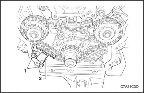
Camshaft primary drive chain
1. Remove the secondary timing chain for cylinder bank 1. See "Camshaft Drive Chain Components" in this section.
2. Remove the two bolts (1) of the primary timing chain tensioner and remove the tensioner (2).
Note: Use caution when removing the tensioner bolts. The tensioner plunger may spring back and pop out when the tensioner is removed.
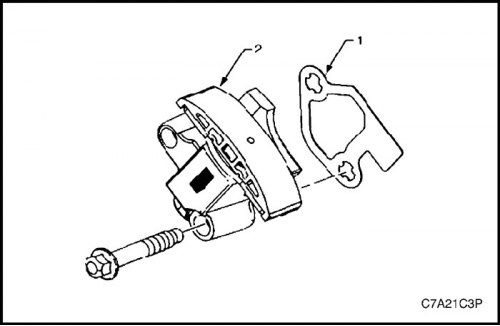
3. Remove the gasket (1) from the tensioner (2) and discard it.
4. Inspect the cylinder block surface where the primary timing chain tensioner will be installed for any burrs that may affect the seal of the new tensioner gasket.
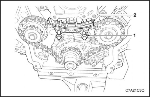
5. Remove the two bolts (1) of the upper primary timing chain guide and remove the guide (2).
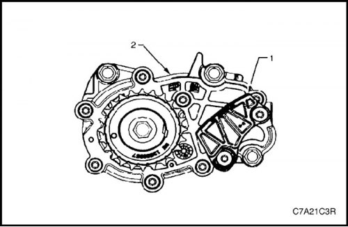
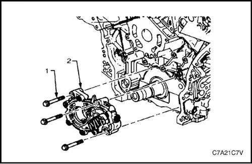
Note: Do not remove the lower guide (1) of the primary timing chain. The lower guide is not intended for separate maintenance. If the lower guide of the primary timing chain needs to be replaced, the oil pump (2) must be replaced as an assembly.
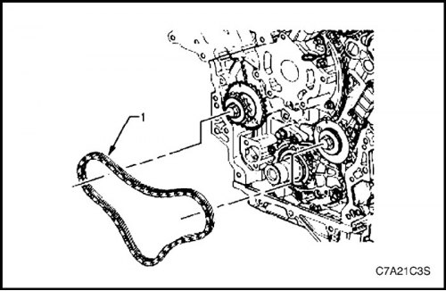
6. Remove the primary camshaft drive chain (1).
Note: To facilitate removal, remove the chain from the crankshaft sprocket before removing it from the intermediate drive shaft sprockets.
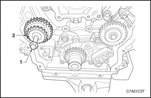
7. If necessary, remove the bolt (1) of the intermediate shaft sprocket of the camshaft drive of cylinder bank 1, and then remove the sprocket (2).
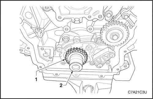
8. If necessary, remove the sprocket (1) from the crankshaft (2).
Secondary timing chain for camshafts, cylinder bank 2
1. Remove the primary timing chain. See "Camshaft Drive Chain Components" in this section.
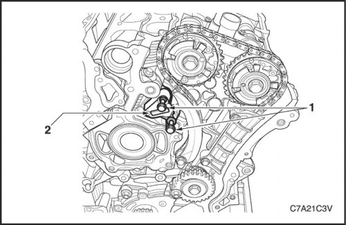
2. Remove the two bolts (1) of the secondary timing chain tensioner for cylinder bank 2 and remove the tensioner (2).
Note: Use caution when removing the tensioner bolts. The tensioner plunger may spring back and pop out when the tensioner is removed.
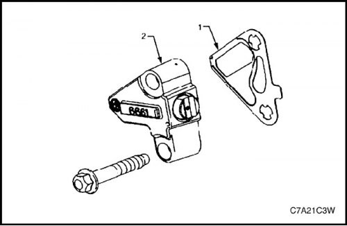
3. Remove the gasket (1) from the tensioner (2) and discard it.
4. Inspect the tensioner mounting surface on the Bank 2 cylinder head for burrs or other defects that may affect the seal of the new tensioner gasket.
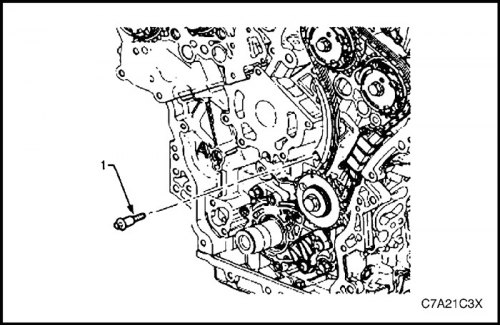
5. Remove the bolt (1) of the secondary timing chain shoe for cylinder bank 2.
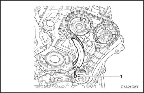
6. Remove the shoe (1) of the secondary drive chain of the camshafts of cylinder bank 2.
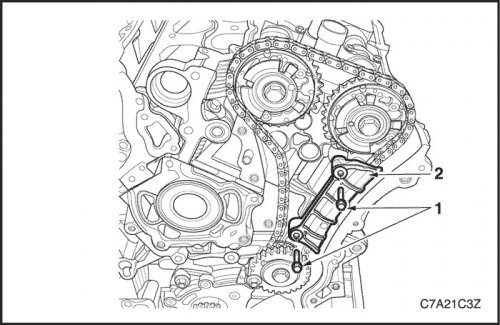
7. Remove the bolt (1) of the secondary drive chain guide for cylinder bank 2 camshafts and remove the guide (2).
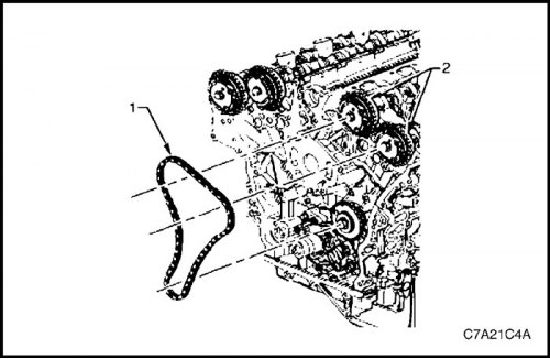
8. Remove the chain (1) of the secondary drive of the camshafts of cylinder bank 2 from the drives (2) for adjusting the valve timing and from the sprocket of the intermediate shaft of the camshaft drive.
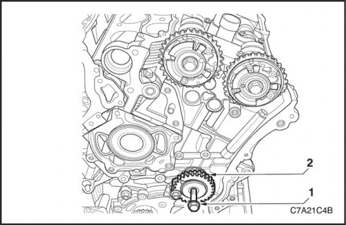
9. If necessary, remove the bolt (1) of the intermediate shaft sprocket of the camshaft drive of cylinder bank 2, and then remove the sprocket (2).
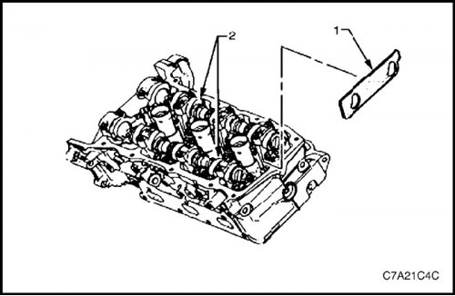
10. Remove tool EN 46105-2 (1) from camshafts (2) of cylinder bank 2.
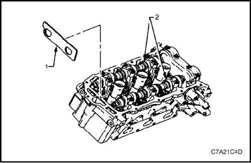
11. Remove tool EN 46105-1 (1) from camshafts (2) of cylinder bank 1.
Clear, clean
1. Clean all of the following components with a suitable solvent:
- crankshaft sprocket,
- primary camshaft drive chain,
- primary camshaft drive chain guide,
- primary camshaft drive chain tensioner,
- secondary camshaft drive chains,
- secondary camshaft drive chain shoes,
- secondary camshaft drive chain guides,
- secondary timing chain tensioners and
- bolts.
2. Dry all components with compressed air.
Inspection
Camshaft drive chains
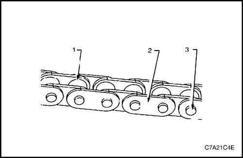
1. Inspect the primary and/or secondary camshaft drive chains for the following faults:
- jamming or wear of rollers (1),
- loosely bonded plates (2), and
- weakly held axles (3).
2. Replace a damaged camshaft timing chain if necessary.
Intermediate shaft sprockets for camshaft drive
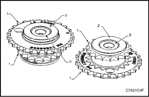
1. Inspect the intermediate camshaft sprockets for the following faults:
- Damage to the primary or secondary drive sprocket (1).
- Damage to the bearing (2) of the hub. Check whether the bearing rotates freely. If there is wobbling, noise or uneven rotation when the bearing rotates, the intermediate sprocket should be replaced.
- Damage to the seating/sealing surface for the bolt head (3).
- Damage to the sealing surface of the bearing hub contact with the cylinder block.
- Inspect the valve timing drive assemblies. See "Valve timing drive assembly" in this section.
Crankshaft sprockets
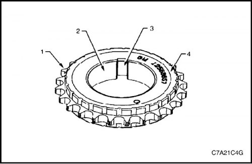
1. Inspect the crankshaft sprocket for the following faults:
- damage to the sprocket (1),
- damage to the hole (2),
- damage to the keyway (3),
- damage to the material of the supporting surface (4).
2. Replace damaged sprocket if necessary.
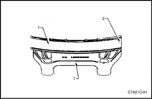
Upper Primary Timing Chain Guide
1. Inspect the upper primary timing chain guide for the following conditions:
- wear of the guide surface (1),
- crack or fracture of the guide surface (2),
- crack or damage to the base of the guide (3).
2. Replace damaged guide if necessary.
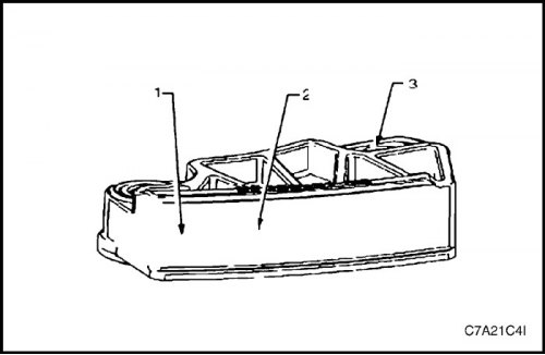
Lower Primary Timing Chain Guide
1. Inspect the upper primary timing chain guide for the following conditions:
- wear of the guide surface (1),
- crack or fracture of the guide surface (2),
- crack or damage to the base of the guide (3).
Note: The lower primary timing chain guide is not serviceable separately and is an integral part of the oil pump assembly.
2. Replacing the lower primary timing chain guide is accomplished by replacing the oil pump. See "Oil pump assembly" in this section.
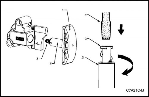
Primary Timing Chain Tensioner
1. Inspect the primary timing chain tensioner, checking that the shoe surface (1) is not worn.
2. Inspect the tensioner, checking whether the tensioner shaft (2) is blocked or jammed. Set the plunger (3) to its original position and make sure that the tensioner shaft moves freely in and out of the tensioner housing.
Note: To reset the tensioner, use a flat-head screwdriver of the appropriate size (4) and rotate the plunger clockwise until it is inserted into the tensioner shaft.
3. Replace damaged tensioner if necessary.
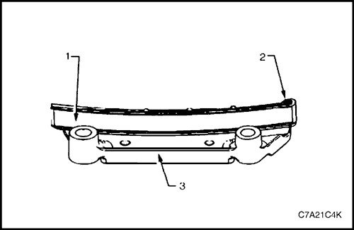
Secondary timing chain guide for cylinder bank 2
1. Inspect the secondary timing chain guide for cylinder bank 2 for the following faults:
- wear of the guide surface (1),
- crack or fracture of the guide surface (2),
- crack or damage to the base of the guide (3).
2. Replace the damaged guide if necessary. Set the plunger (3) to its original position and make sure that the tensioner shaft moves freely in and out of the tensioner housing.
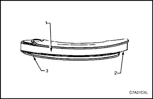
Secondary timing chain shoe for cylinder bank 2
1. Inspect the front of the secondary timing chain shoe for bank 2 camshafts for the following faults:
- wear of the shoe surface (1),
- crack or fracture of the shoe surface (2),
- crack or damage to the shoe (3).
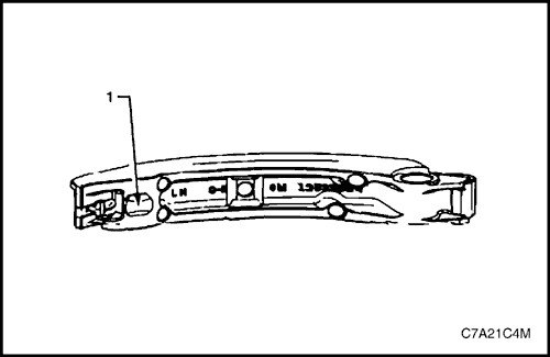
2. Inspect the shoe from the rear, checking for damage or wear and that the tensioner contact pad (1) is not missing.
3. Replace the damaged shoe if necessary.
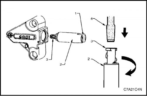
Secondary Timing Chain Tensioner Bank 2
1. Inspect the secondary timing chain tensioner for cylinder bank 2, checking that the contact surface of the plunger and shoe (1) is not damaged.
2. Inspect the tensioner, checking whether the tensioner shaft (2) is blocked or jammed. Set the plunger (3) to its original position and make sure that the tensioner shaft moves freely in and out of the tensioner housing.
Note: To reset the tensioner, use a flat-head screwdriver of the appropriate size (4) and rotate the plunger clockwise until it is inserted into the tensioner shaft.
3. Replace damaged tensioner if necessary.
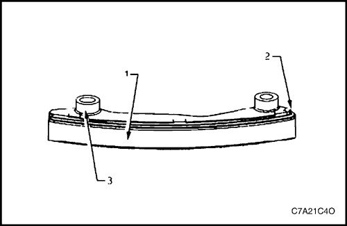
Secondary timing chain guide for cylinder bank 1
1. Inspect the secondary timing chain guide for cylinder bank 1 for the following faults:
- wear of the guide surface (1),
- crack or fracture of the guide surface (2),
- crack or damage to the base of the guide (3).
2. Replace damaged guide if necessary.
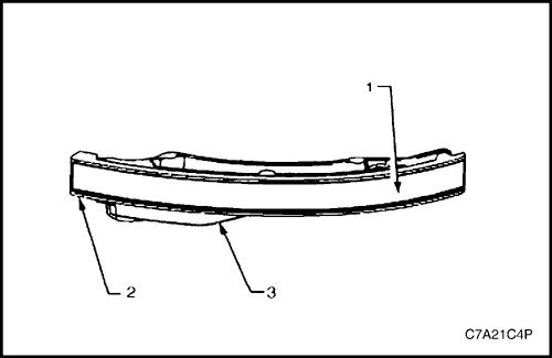
Secondary timing chain shoe for cylinder bank 1
1. Inspect the front of the secondary timing chain shoe for cylinder bank 1 for the following faults:
- wear of the shoe surface (1),
- crack or fracture of the shoe surface (2),
- crack or damage to the shoe (3).
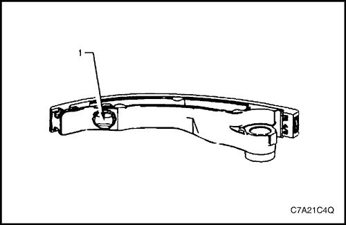
2. Inspect the shoe from the rear, checking for damage or wear and that the tensioner contact pad (1) is not missing.
3. Replace the damaged shoe if necessary.
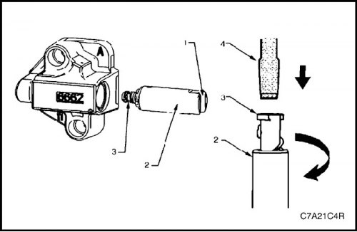
Secondary Timing Chain Tensioner for Cylinder Bank 1
1. Inspect the secondary timing chain tensioner for cylinder bank 1, checking that the contact surface of the plunger and shoe (1) is not damaged.
Note: To reset the tensioner, use a flat-head screwdriver of the appropriate size (4) and rotate the plunger clockwise until it is inserted into the tensioner shaft.
2. Inspect the tensioner, checking whether the tensioner shaft (2) is blocked or jammed. Set the plunger (3) to its original position and make sure that the tensioner shaft moves freely in and out of the tensioner housing.
3. Replace damaged tensioner if necessary.
Installation procedure
Bank 2 camshaft timing chain components
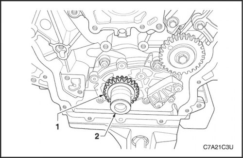
1. Install the crankshaft sprocket (1) onto the shaft (2), aligning the keyway with the key on the shaft.
2. Move the sprocket along the crankshaft until it contacts the shoulder on the shaft.
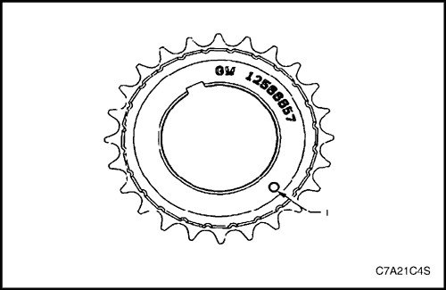
Note: Ensure that the crankshaft sprocket is positioned so that the timing mark (1) is visible.
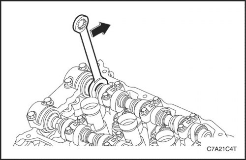
Caution! To install the EN 46105 device on the camshafts, turn the shafts counterclockwise. It is not necessary to turn the shafts more than 45 degrees.
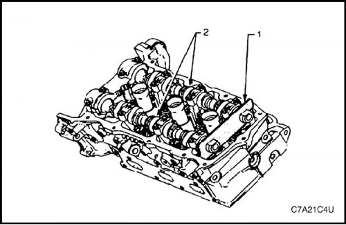
3. Fit tool EN 46105-1 (1) to the rear ends of the camshafts (2) of cylinder bank 2 and fit tool EN 46105-2 to the rear ends of the camshafts of cylinder bank 1.
Caution! Before installing the camshaft drive chains, all shafts must be locked in place.
4. Ensure that the EN 46105 tool is fully seated on the camshafts.
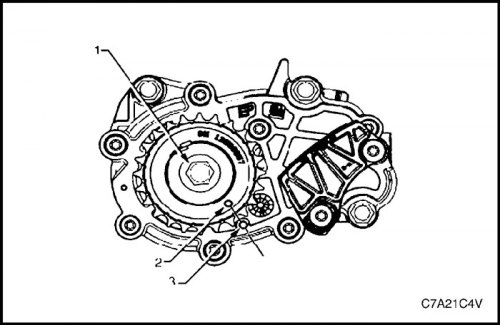
5. Using the EN-46111 tool (1), turn the crankshaft clockwise until the timing mark (2) on the crankshaft sprocket is aligned with the mark (3) on the oil pump housing.
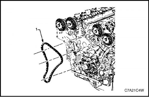
6. Install the secondary timing chain (1) for cylinder bank 2, positioning the chain as follows:
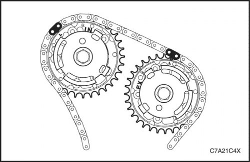
A. Place the chain on both sprockets of the camshaft timing drive for cylinder bank 2.
B. Position the two shiny chain links over each of the variable valve timing drive sprockets.
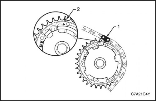
Caution! When adjusting the chain position on the camshaft timing drive sprockets for cylinder bank 2, use the circle-shaped timing marks, NOT the triangle-shaped ones.
C. Align the bright link (1) of the camshaft drive chain with the round timing mark (2) on the exhaust camshaft timing drive sprocket for cylinder bank 2.
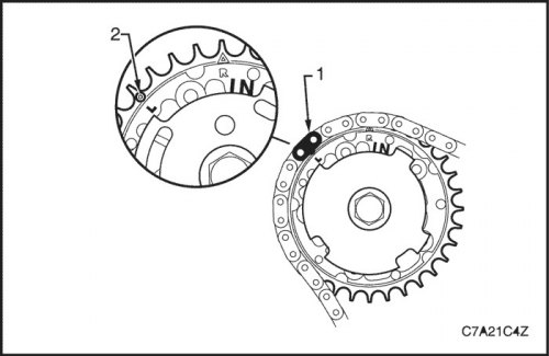
D. Align the bright link (1) of the camshaft timing chain with the round timing mark (2) on the intake camshaft timing drive sprocket.
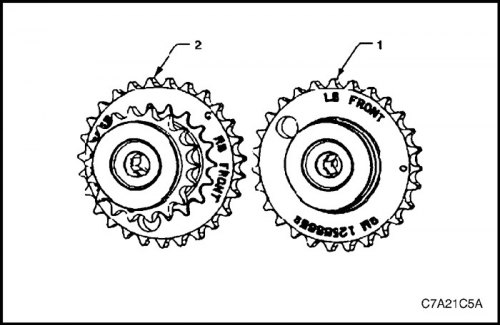
Caution! The sprocket (1) of the intermediate shaft of the camshaft drive of cylinder bank 2 is marked with the letters LB and "FRONT", and the sprocket (2) of the intermediate shaft of the camshaft drive of cylinder bank 1 is marked with the letters RB and "FRONT". It is necessary not to mix up the sprockets and to arrange them during installation so that the word "FRONT" faces forward.
7. Ensure correct selection and orientation of the intermediate shaft sprocket for the camshaft drive of cylinder bank 2.
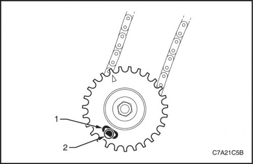
8. Place the secondary timing chain for bank 2 camshafts around the left-hand inner sprocket of the intermediate shaft, aligning the bright link (1) of the chain with the hole (2) in the outer sprocket.
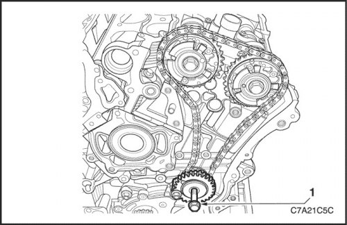
9. Install the intermediate shaft sprocket of the camshaft drive of cylinder bank 2 onto the cylinder block.
Tighten
Tighten the intermediate shaft sprocket retaining bolt to 66 N·m (49 lb-ft).
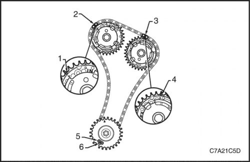
10. Check alignment of installation marks (from 1st to 6th) secondary drive chains of camshafts of cylinder bank 2
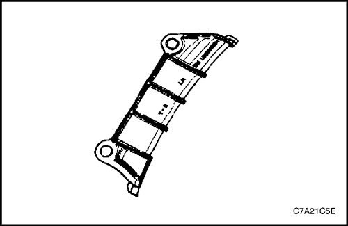
Caution! The secondary timing chain guide for cylinder bank 2 is marked with the letters LH. When installing the shoe on the cylinder bank 2 side, use the appropriate shoe and ensure that the letters LH face the front of the vehicle when installing.
11. Ensure correct selection and orientation of the secondary drive chain guide for cylinder bank 2 camshafts.
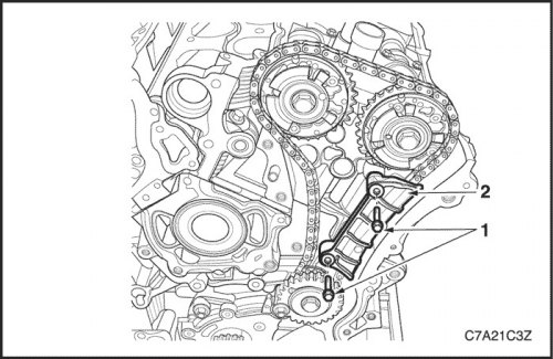
12. Install the guide (1) of the secondary drive chain of the camshafts of cylinder bank 2.
Tighten
Tighten the secondary drive chain guide bolt to 23 N·m (17 lb-ft).
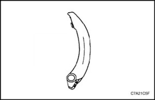
Caution! The shoe (2) of the secondary timing chain for cylinder bank 2 is marked with the letters LH on the back. When installing the shoe on the cylinder bank 2 side, the appropriate shoe must be used.
13. Ensure that the secondary timing chain shoe for cylinder bank 2 is correctly selected and oriented.
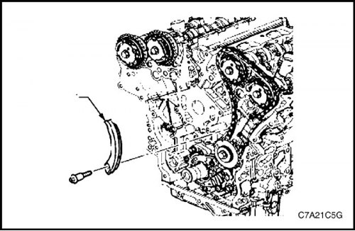
14. Install the shoe (1) of the secondary drive chain of the camshafts of cylinder bank 2.
Note: Before tightening the mounting bolt, ensure that the secondary timing chain shoe does not contact the secondary timing chain tensioner mounting pad for bank 2 camshafts.
Tighten
Tighten the bank 2 secondary timing chain shoe bolt to 23 N·m (17 lb-ft).
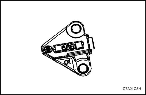
15. Ensure that the secondary timing chain tensioner for cylinder bank 2 is selected and oriented correctly.
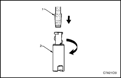
16. Reset the secondary timing chain tensioner for cylinder bank 2.
Note: To reset the tensioner, use a flat-head screwdriver of the appropriate size (1) and rotate the plunger clockwise until it enters the tensioner shaft (2).
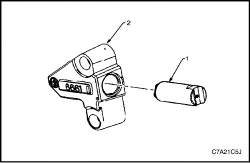
17. Install the tensioner shaft (1) into the housing (2) of the secondary drive chain tensioner for the camshafts of cylinder bank 2.
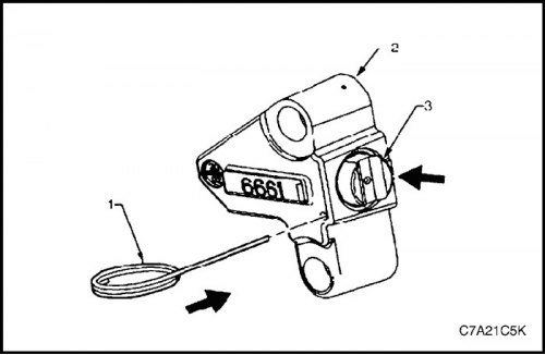
Caution! If the EN 46112 tool (1) is not inserted into the tensioner housing (2), the tensioner shaft (3) will remain in the locked position and the camshaft timing chain will not be tensioned, which will result in engine damage.
18. Press the tensioner shaft into the housing and lock the secondary drive chain tensioner for cylinder bank 2 by inserting the EN 46112 tool into the hole provided in the side wall of the tensioner housing.
19. Slowly release the secondary timing chain tensioner shaft for cylinder bank 2. The tensioner should remain in its original position.
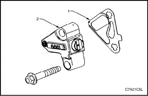
20. Install a new gasket (1) on the tensioner (2) of the secondary drive chain of the camshafts of cylinder bank 2.
21. Install the Bank 2 secondary timing chain tensioner bolts through the holes in the tensioner and gasket.
22. Ensure that the Bank 2 cylinder head mounting surface for the secondary timing chain tensioner is free of nicks or other defects that could affect the seal of the new tensioner gasket.
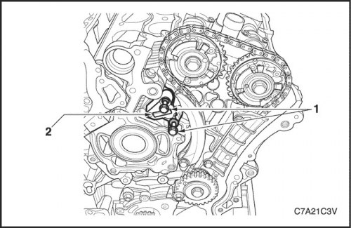
23. Install the tensioner (2) of the secondary drive chain of the camshafts of cylinder bank 2 in place and tighten the bolts (1) securing it to the cylinder head.
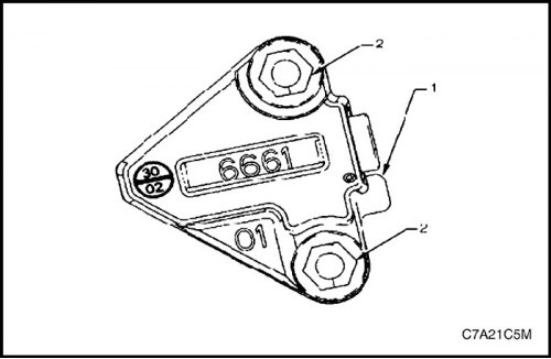
24. Check the correct position of the tongue (1) of the secondary drive chain tensioner gasket for cylinder bank 2.
25. Tighten the bolts (2) of the secondary timing chain tensioner for cylinder bank 2.
Tighten
Tighten the bank 2 secondary timing chain tensioner mounting bolts to 23 N·m (17 lb-ft).
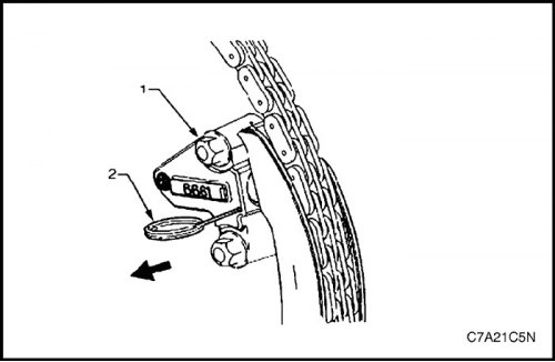
26. Unlock the tensioner (1) by pulling out the EN 46112 tool (2) and releasing the tensioner shaft.
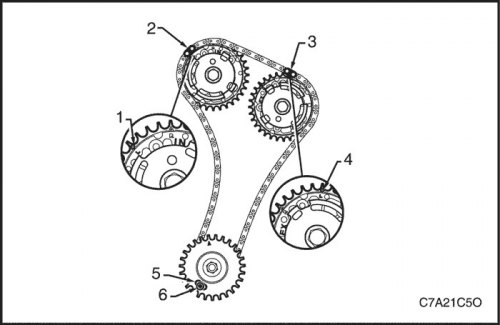
27. Check alignment of installation marks (from 1st to 6th) secondary drive chains of camshafts of cylinder bank 2
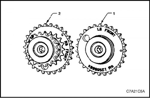
Primary Timing Chain Components
1. Install the Bank 2 secondary timing chain components if previously removed. See "Camshaft Drive Chain Components" in this section.
Attention! The sprocket (2) of the intermediate shaft of the camshaft drive of cylinder bank 1 is marked with the letters RB and "FRONT", and the sprocket (1) of the intermediate shaft of the camshaft drive of cylinder bank 2 is marked with the letters RB and "FRONT". It is necessary not to mix up the sprockets and to arrange them during installation so that the word "FRONT" faces forward.
2. Ensure that the intermediate shaft sprocket of the camshaft drive for cylinder bank 1 is correctly selected and oriented.
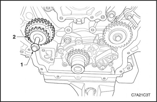
3. Install the sprocket (2) of the intermediate shaft of the camshaft drive of cylinder bank 1.
Tighten
Tighten the bank 1 camshaft intermediate shaft sprocket retaining bolt to 65 N·m (48 lb-ft).
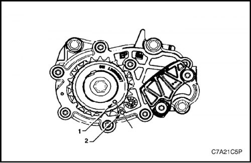
4. Make sure that the timing mark (1) on the crankshaft sprocket is aligned with the mark (2) on the oil pump housing.
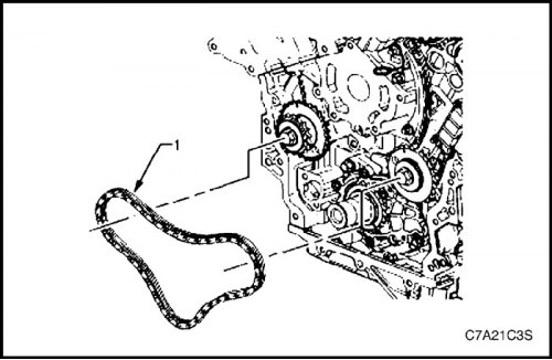
5. Install the primary camshaft drive chain (1).
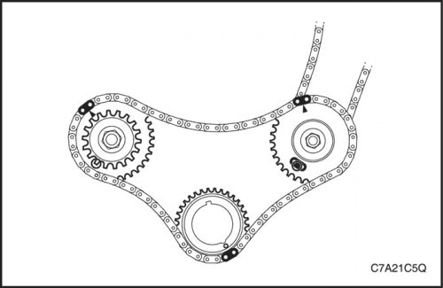
6. Place the primary camshaft drive chain over the large sprockets of each intermediate shaft and over the crankshaft sprocket, ensuring that the bright links of the chains are in the following position:
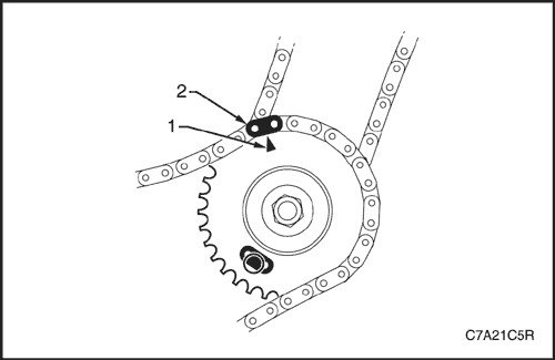
A. The timing mark (1) of the intermediate shaft sprocket of the camshaft drive of cylinder bank 2 is aligned with the bright link (2) of the primary camshaft drive chain.
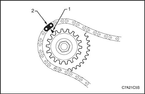
B. The timing mark (1) of the intermediate shaft sprocket of the camshaft drive of cylinder bank 1 is aligned with the bright link (2) of the primary camshaft drive chain.
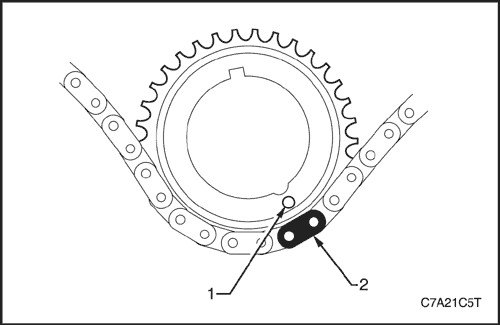
C. The timing mark (1) of the crankshaft sprocket is aligned with the bright link (2) of the drive chain.

7. Make sure that all timing marks (1, 2 and 3) are aligned with the corresponding bright links (4, 5 and 6) of the camshaft drive chain.
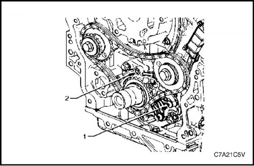
Note: Do not remove the lower guide (1) of the primary timing chain. The lower guide is not intended for separate maintenance. If the lower guide of the primary timing chain needs to be replaced, the oil pump (2) must be replaced as an assembly.
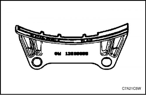
8. Ensure that the primary drive chain guide of the camshafts is selected and oriented correctly.
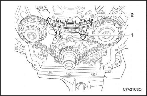
9. Install the upper guide (1) of the primary camshaft drive chain.
10. Install the bolts (2) of the upper primary timing chain guide.
Tighten
Tighten the primary drive chain guide bolts to 23 N·m (17 lb-ft).
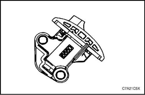
11. Install the primary timing chain tensioner.
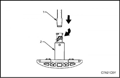
12. Reset the primary timing chain tensioner to its original position.
Note: To reset the tensioner, use a flat-head screwdriver of the appropriate size (1) and rotate the plunger clockwise until it enters the tensioner shaft (2).
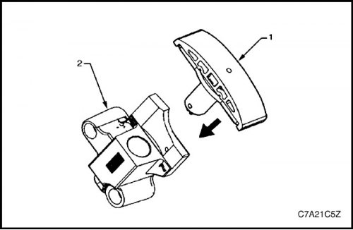
13. Install the tensioner shoe assembly (1) into the primary camshaft drive tensioner housing (2).
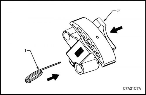
Caution! If the EN 46112 (1) tool is not inserted into the tensioner housing, the tensioner plunger will remain in the locked position and the camshaft chain will not be tensioned, which will result in engine damage.
14. Press the shoe assembly into the housing (2) and lock the primary drive chain tensioner by inserting the EN 46112 tool into the hole provided in the side wall of the housing.
15. Slowly release the pressure on the primary timing chain tensioner. The primary timing chain tensioner should remain in the depressed position.
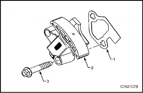
16. Install a new gasket (1) on the primary timing chain tensioner (2).
17. Install bolts (3) through the holes in the tensioner and gasket.
18. Ensure that the cylinder block mounting surface intended for the primary drive chain tensioner is free of burrs or other defects that could affect the seal of the new tensioner gasket.
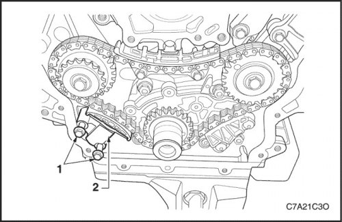
19. Install the tensioner (2) of the primary camshaft drive chain in place and tighten the bolts (1) securing it to the cylinder block.
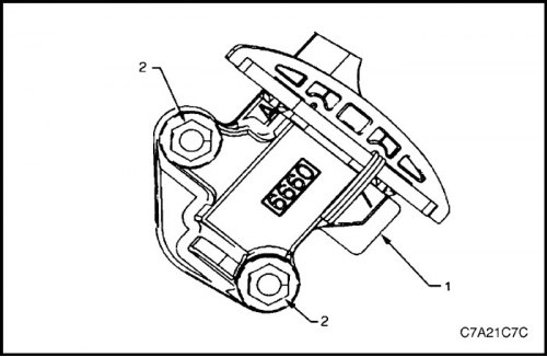
20. Check the correct position of the tongue (1) of the primary camshaft drive chain tensioner gasket.
21. Tighten the bolts (2) of the primary camshaft drive chain tensioner.
Tighten
Tighten the primary drive chain tensioner mounting bolts to 23 N·m (17 lb-ft).
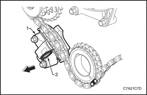
22. Unlock the tensioner (1) by pulling out the EN 46112 tool (2) and releasing the tensioner shaft.
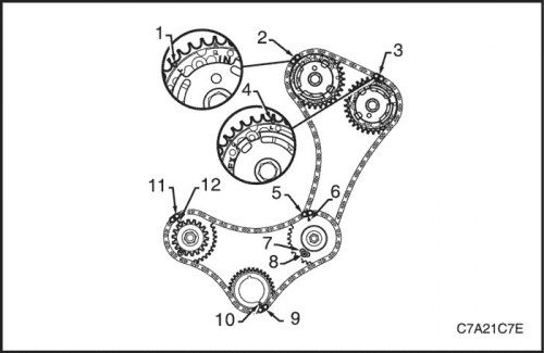
23. Check alignment of installation marks (from 1st to 12th) primary and secondary drive chains of camshafts of cylinder bank 2
24. Remove tool EN 46105 from camshafts of cylinder banks 2 and 1.
Bank 1 Secondary Timing Chain Components
1. Install the primary timing chain components. See "Camshaft Drive Chain Components" in this section.
2. Using the EN-46111 tool (1), turn the crankshaft clockwise until the timing mark (2) on the crankshaft sprocket is aligned with the mark (3) on the oil pump housing.
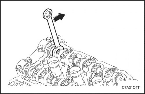
Caution: Rotate the camshafts to fit the EN 46105 tool onto them. This does not require turning the shafts more than 45 degrees.
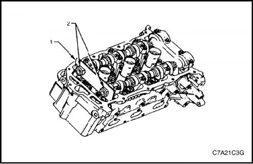
3. Fit the EN 46105-1 tool (1) to the rear ends of the camshafts (2) of cylinder bank 1.
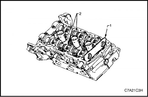
4. Fit the EN 46105-2 tool (1) to the rear ends of the camshafts (2) of cylinder bank 2.
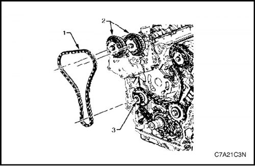
5. Install the chain (1) of the secondary drive of the camshafts of cylinder bank 1 on the drives (2) for adjusting the valve timing and on the sprocket (3) of the intermediate shaft.
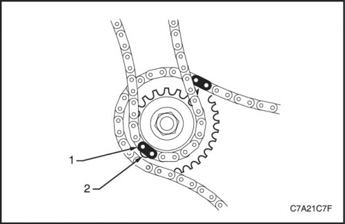
A. Place the secondary timing chain around the outer sprocket of the intermediate camshaft for bank 1, aligning the bright link (1) of the chain with the hole (2) in the inner sprocket.
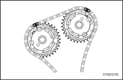
B. Place the chain on both sprockets of the camshaft timing drive for cylinder bank 1.
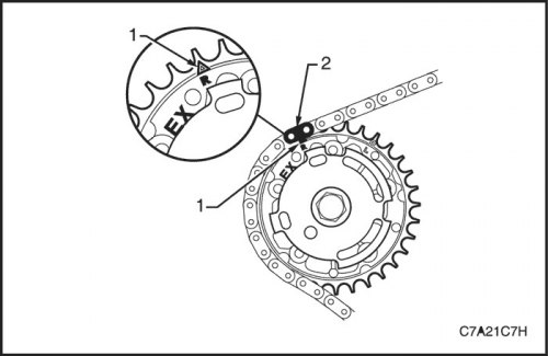
Caution! When adjusting the chain position on the camshaft timing drive sprockets for cylinder bank 1, use the triangle-shaped (1) timing marks, NOT the circle-shaped ones.
C. Align the bright link (2) of the chain with the triangular timing mark on the exhaust valve timing drive sprocket.
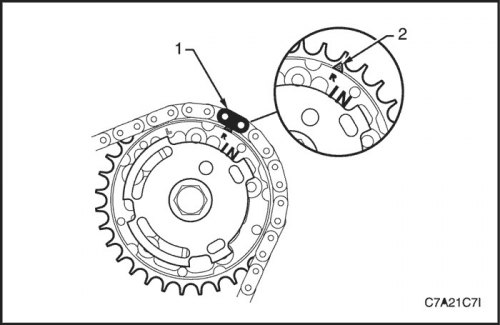
D. Align the bright link (1) of the chain with the triangular timing mark (2) on the intake camshaft timing drive sprocket.
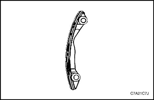
Caution: When installing the chain guide on the bank 1 side, ensure that the bank 1 secondary camshaft chain guide is used.
6. Ensure correct selection and orientation of the secondary drive chain guide for camshafts of cylinder bank 1.
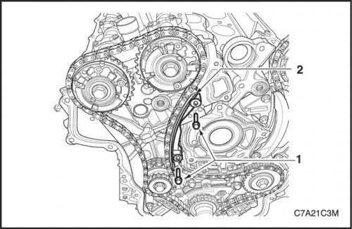
7. Place the chain guide (2).
8. Ensure that the primary drive chain guide of the camshafts is selected and oriented correctly.
Tighten
Tighten the secondary drive chain guide bolts to 23 N·m (17 lb-ft).
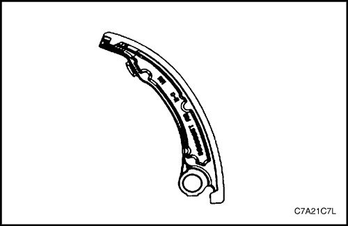
Caution! The secondary timing chain shoe for bank 1 is marked with the letters RH. When installing the shoe on the bank 1 side, use the appropriate shoe and ensure that the letters RH face the front of the vehicle when installing.
9. Ensure that the secondary timing chain shoe for cylinder bank 1 is correctly selected and oriented.
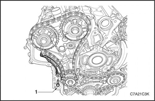
10. Position the shoe (1) of the secondary timing chain of the camshafts of cylinder bank 1.
Tighten
Tighten the bank 1 secondary timing chain shoe bolt to 23 N·m (17 lb-ft).
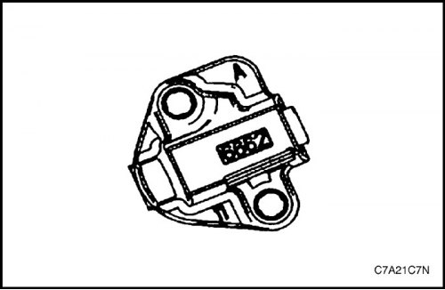
11. Ensure that the secondary timing chain tensioner for cylinder bank 1 is selected and oriented correctly.
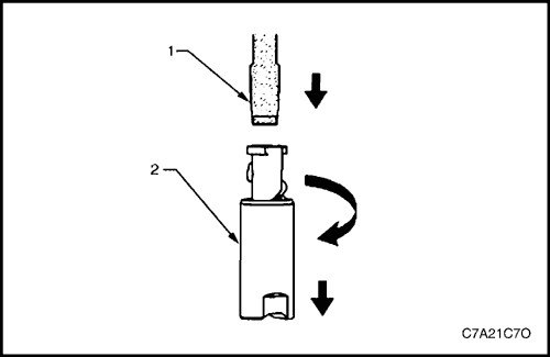
12. Reset the secondary timing chain tensioner for cylinder bank 1.
Note: To reset the tensioner, use a flat-head screwdriver of the appropriate size (1) and rotate the plunger clockwise until it enters the tensioner shaft (2).
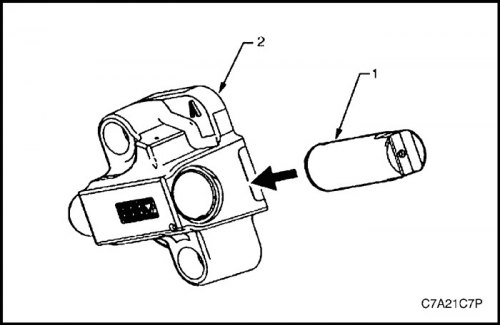
13. Install the tensioner shaft (1) into the housing (2) of the secondary drive chain tensioner of the camshafts of cylinder bank 1.
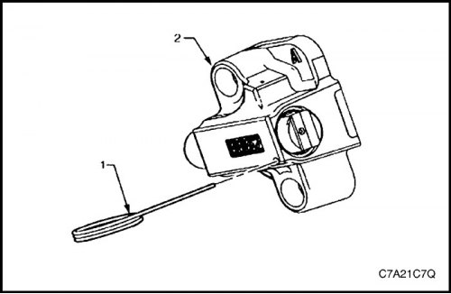
Caution! If the EN 46112 tool (1) is not inserted into the tensioner housing (2), the tensioner plunger will remain in the locked position and the camshaft timing chain will not be tensioned, which will result in engine damage.
14. Press the tensioner shaft into the housing and lock the tensioner by inserting the EN 46112 device into the designated hole in the side wall of the tensioner housing.
15. Slowly release the secondary timing chain tensioner shaft for cylinder bank 1. The tensioner should remain in its original position.
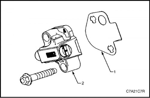
16. Install a new gasket (1) on the tensioner (2) of the secondary drive chain of the camshafts of cylinder bank 1.
17. Install bolts (3) through the holes in the tensioner and gasket.
18. Ensure that the Bank 1 cylinder head mounting surface for the secondary timing chain tensioner is free of nicks or other defects that could affect the seal of the new tensioner gasket.
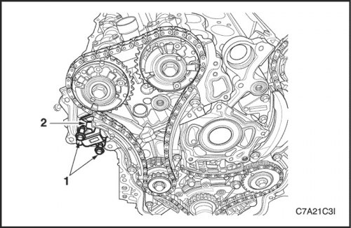
19. Install the tensioner (2) of the secondary drive chain of the camshafts of cylinder bank 1 in place and tighten the bolts (1) securing it to the cylinder block.
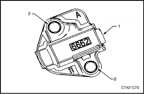
20. Check that the tensioner gasket tongue (1) is positioned correctly.
21. Tighten the bolts (2) of the secondary timing chain tensioner for cylinder bank 1.
Tighten
Tighten the bank 1 secondary timing chain tensioner mounting bolts to 23 N·m (17 lb-ft).
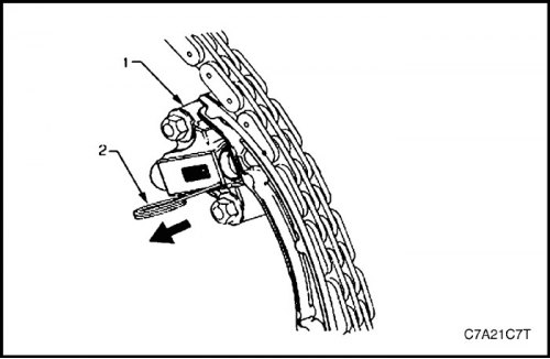
22. Unlock the tensioner (1) by pulling out the EN 46112 tool (2) and releasing the tensioner plunger.
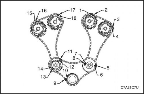
23. Check the alignment of all alignment marks (from 1st to 18th) primary drive chains and secondary drive chains of camshafts.
24. Remove tools EN 46105 and EN 46105-2 from the camshafts of both cylinder heads.
25. Reinstall the spark plugs. See Section 1F3, Engine Controls - HFV6 3.2L.
26. Reinstall the front engine cover. See "Front cover assembly" in this section.
The original text can be found on the website: ChevyMan