


Removal procedure
1. Remove the decorative engine covers. See "Decorative Engine Cover" in this section.
2. Remove the upper intake manifold assembly. See "Intake manifold assembly" in this section.
3. Remove the cylinder head cover. See "Cylinder head cover" in this section.
4. Remove the camshaft position sensors. See Part 1F3, "Engine Controls - HFV6 3.2L" (if available).
5. Remove the variable valve timing (CMP) actuator solenoids. See Part 1F3, "Engine Controls - HFV6 3.2L" (if available).
6. Remove the crankshaft balancer.
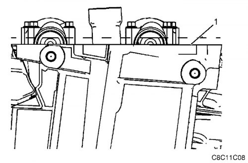
7. Using the EN-46111 tool, rotate the crankshaft so that the camshafts are in neutral position (weak tension). The camshaft flats will be parallel to the mating surface with the timing belt cover (1).
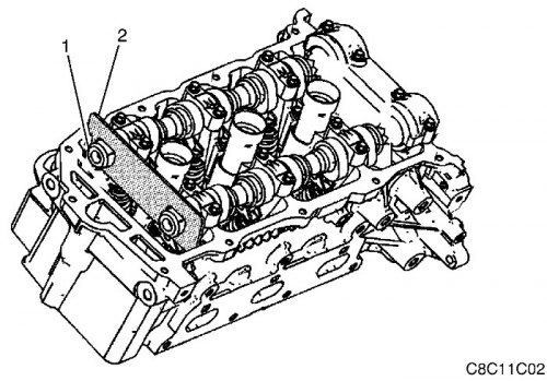
8. Install the EN-46105 tool (1) to the rear of the camshafts on the right side (2).
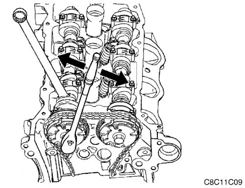
Important:
- To prevent the camshaft/engine from rotating, use an open-end wrench placed on the hexagon of the camshaft.
- DO NOT remove the bolt securing the variable valve timing drive to the camshaft yet.
9. Loosen the bolt securing the right exhaust valve timing drive to the camshaft.
Important: The front engine cover has been removed in the following illustrations for clarity and is not required to perform the procedure.
10. Loosen the EN-48313 tool to retract the struts.
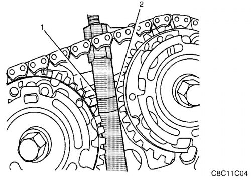
11. Insert the EN-48313 tool between the variable valve timing actuators, behind the timing chain, so that the line engraved on the tool body (1) coincides with the top surface of the cylinder head (2). This is the approximate installation position.
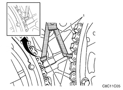
12. Make sure that the feet (2) on the stands (1) of the EN-48313 fixture are facing the front of the engine.
Important: DO NOT TIGHTEN the EN-48313 tool yet.
13. Slightly spread the legs (1) of the EN-48313 fixture by turning the T-handle clockwise.
Important: Ensure that the legs (2) of the EN-48313 tool are securely engaged in the notches of the chain links to prevent the chain from slipping during tightening.
14. Continue to extend the EN-48313 tool until the legs (2) engage the timing chain.
15. Hand tighten the EN-48313 fixture.
Important: DO NOT allow the EN-48313 tool body to rotate while tightening the T-handle.
16. Using an open-end wrench on the hexagon of the EN-48313 fixture body, hand tighten the T-handle.
17. Using an open-end wrench on the hexagons of the right intake and exhaust camshafts, rotate the camshafts towards each other to loosen the chain between the drives.
18. The EN-48313 tool is now correctly positioned to hold the timing chain in position.
Important: Be sure to mark the timing chain and variable valve timing actuators to ensure proper assembly.
19. Mark the timing chain and valve timing drives.
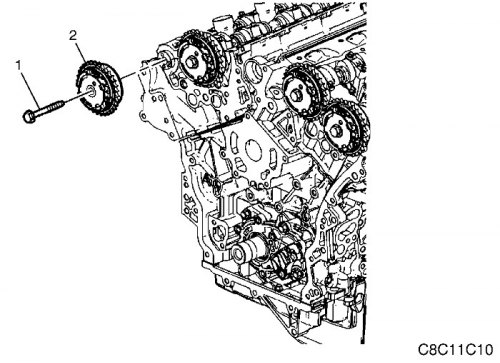
20. Loosen the bolt securing the right exhaust valve timing drive to the camshaft (1).
21. Remove the right exhaust valve timing drive (2).
Installation procedure
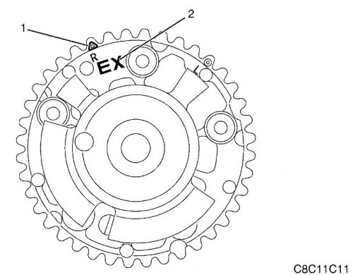
1. Make sure that the correct camshaft timing actuator is installed. Check for the "EX" marking (1) on the camshaft timing actuator housing. This marking identifies the exhaust camshaft timing actuator.
2. Make sure to use the correct timing mark. Observe the "R" mark on the outer ring of the variable valve timing drive and the triangular mark (2). These marks are designed to align with the highlighted link of the timing chain on the right side of the engine.
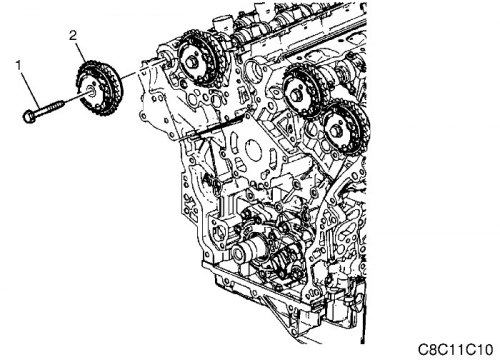
3. Install the right exhaust valve timing actuator (2).
Important:
- Make sure that the marks on the valve timing drives and the timing chain match.
- DO NOT TIGHTEN the right intake camshaft timing actuator mounting bolt to the camshaft yet (1).
4. Tighten the bolt securing the right valve timing drive to the camshaft (1).
- DO NOT TIGHTEN completely yet.
5. Remove the EN-48313 fixture.
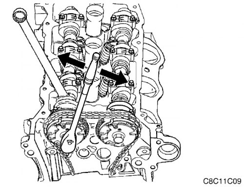
Important: To prevent the camshaft/engine from rotating, use an open-end wrench placed on the hexagon of the camshaft.
6. Tighten the bolt securing the variable valve timing drive to the camshaft.
Tighten
Tighten the bolt to 58 N·m (43 lb-ft).
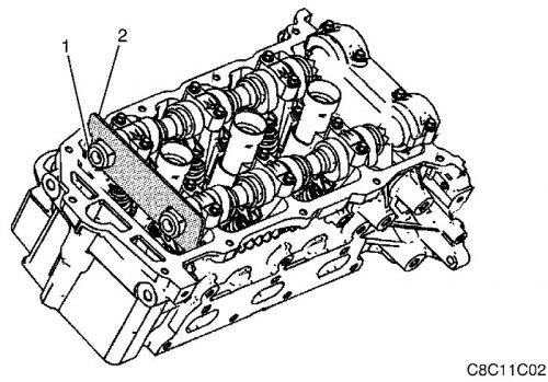
7. Remove tool EN-46105 (2) from the rear of the right-hand camshafts (1).
8. Install the variable valve timing (CMP) actuator solenoids. See Part 1F3, "Engine Controls - HFV6 3.2L" (if available).
9. Install the camshaft position sensors. See Part 1F3, "Engine Controls - HFV6 3.2L" (if available).
10. Install the crankshaft balancer.
11. Install the cylinder head cover. See "Cylinder head cover" in this section.
12. Install the intake manifold assembly. See "Intake manifold assembly" in this section.
13. Install the decorative engine covers. See "Decorative Engine Cover" in this section.
[The source of the article is available on the website: chevyman.ru]