
It is necessary to take into account that failure of the timing belt (breakage or shear of teeth) may lead to the valves hitting the pistons due to misalignment of the crankshaft and camshaft rotation angles and, as a consequence, to costly engine repairs.
The surface of the toothed part of the belt should not have folds, cracks, undercuts of the teeth and delamination of the fabric from the rubber. The reverse side of the belt should not have wear that exposes the cord threads and signs of burning.
There should be no delamination or fraying on the end surfaces of the belt. If there is damage, the belt must be replaced.
The belt also needs to be replaced if traces of oil are found on it (before replacing the belt, the cause of its oiling should be eliminated) or when replacing a failed tensioner and support roller of the belt, coolant pump.
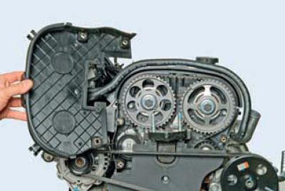
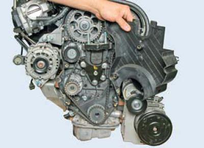
For clarity, we show most of the operations for checking the condition and replacing the timing belt on a dismantled engine.
Remove the air filter (see Removal the air filter).
To check the condition of the timing belt…
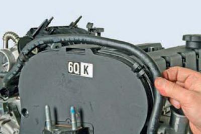
…we remove the coolant supply hose to the throttle assembly from the two holders of the upper front timing drive cover.
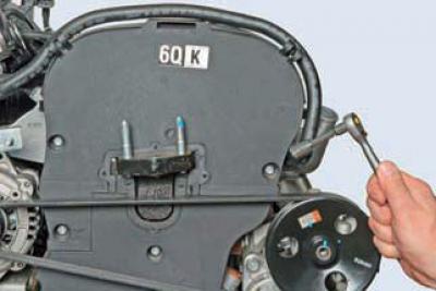
Using a 10 mm socket head, unscrew the three bolts securing the upper front timing belt cover.
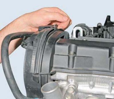
We press the top…
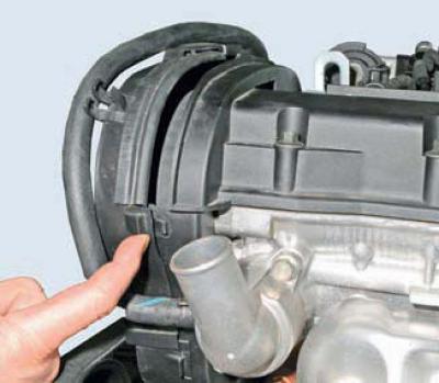
…and two side ones (one on each side) lid retainer…
…and we take it off.
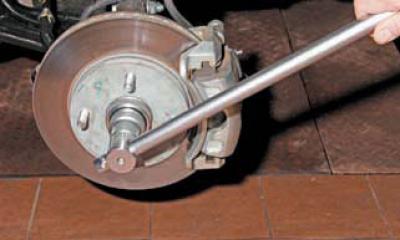
We engage the fifth gear in the gearbox and hang up the right front wheel. Rotating the wheel clockwise, we turn the crankshaft and check the condition of the timing belt.
With normal belt tension…
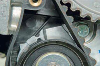
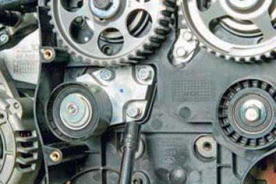
…the movable roller indicator must coincide with the fixed indicator on the tensioner bracket.
Timing Belt Tensioner: Fixed Pointer; bracket; eccentric roller; movable pointer.
If the movable pointer is offset relative to the fixed one: – counterclockwise – the belt tension is insufficient; – clockwise – the belt is too tight.
In both cases, the belt tension should be adjusted (see below) or the belt should be replaced with a new one.
To replace the belt, remove the right front wheel and securely fix the car on a factory-made stand.
Remove the accessory drive belt (see Replacement of auxiliary drive belt).
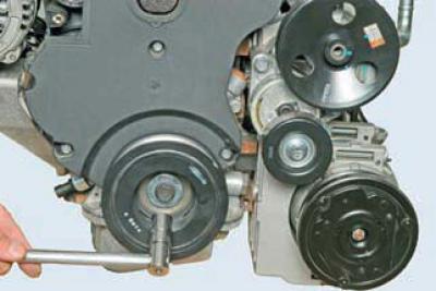
Using a 17 mm head, turn the crankshaft clockwise using the bolt securing the auxiliary drive pulley…
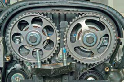
…until the timing marks on the camshaft pulleys are aligned.
We unscrew the bolt securing the auxiliary drive pulley. To keep the crankshaft from turning, the assistant should engage fifth gear and press the brake pedal.
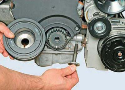
We take out the bolt with the washer and remove the auxiliary drive pulley.
Once again, we check the alignment of the timing marks on the camshaft pulleys. If the valve timing is set correctly…
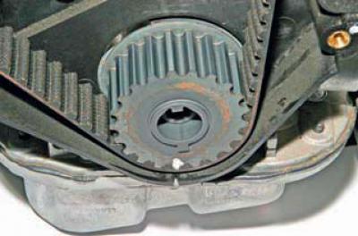
…the mark on the crankshaft pulley should be located opposite the slot on the rear timing drive cover.
Using a 10 mm socket, unscrew the three bolts securing the lower front timing belt cover…
…and remove the lid.
We place a support under the engine oil pan and, having unscrewed the bolts and nuts, remove the bracket of the right support of the power unit (see Replacing the powertrain mounts).
To remove the belt from the pulleys, you need to reduce its tension. To do this, turn the coolant pump housing counterclockwise in the cylinder block socket with the pump mounting screws loosened.
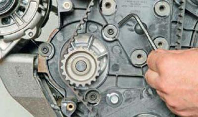
Using a 5 mm Allen key, loosen the three screws securing the coolant pump.
To prevent coolant leakage through the pump sealing ring, loosen the screws only to the point where the pump body can be turned using a tool.
The pump can be turned using a 41 mm open-end wrench on the hexagon on its body.
If there is no such key, turn the pump body..
...using hexagonal sliding pliers..
…or using a 12 mm open-end wrench and a ratchet – by the rib on the pump body.
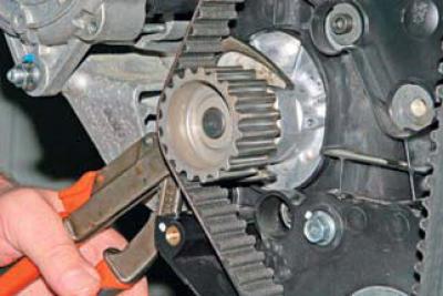
By loosening the belt tension..
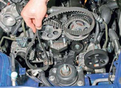
…we remove it from the coolant pump pulleys, camshafts and crankshafts.
Before installing a new belt, check the condition of the coolant pump, tensioner roller and belt support roller.
When rocking and rotating the pump pulley and rollers by hand, there should be no play, jamming, or noise in the bearings. If the above faults are present, replace the damaged parts with new ones.
To replace the tensioner with the roller assembly, remove the cylinder block bracket to which the right support bracket of the power unit is attached (see Removal the coolant pump).
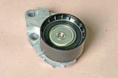
Using a 12 mm socket, unscrew the three bolts securing the tensioner to the cylinder block…
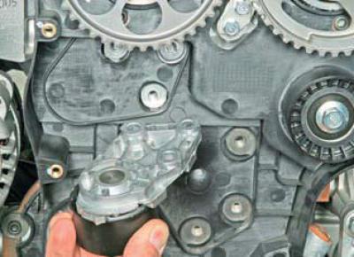
…and remove the belt tensioner.
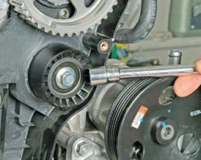
Using a 14 mm socket head, unscrew the support roller mounting bolt…
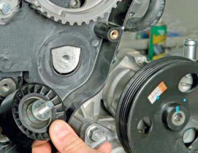
…and we take it off.
Install the tensioner and the belt support roller in the reverse order. Tighten the tensioner and support roller mounting bolts to the specified torques (see Tightening torques for critical threaded connections).
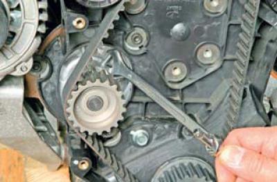
Before installing the belt, make sure that the timing marks on the camshaft pulleys and the mark on the crankshaft pulley are aligned with the slot on the rear timing drive cover. In this position, put the belt on the crankshaft pulley.
While tightening both branches of the belt, we put the front branch behind the support roller, and the rear one, having put it on the coolant pump pulley, behind the tensioner roller. We put the belt on the camshaft pulleys, eliminating the sagging of the belt branches.
We tighten the belt by turning the coolant pump clockwise until the movable and fixed indicators of the tensioner are aligned (see above). In this position, we tighten the pump mounting screws.
With fifth gear engaged, using a 32 mm head, turn the hub bearing mounting nut clockwise and the crankshaft two turns clockwise.
We check the belt tension and the alignment of the timing marks on the crankshaft and camshafts.
If the timing marks do not match, repeat the valve timing operation.
We make sure that there are no leaks from under the coolant pump.
Otherwise, replace the pump body sealing ring (see Removal the coolant pump).
If the valve timing is set correctly and the belt tension is normal, then install the lower front timing cover and the accessory drive pulley. Tighten the accessory drive pulley mounting bolt to the specified torque (see Fig. Tightening torques for critical threaded connections).
Further assembly is carried out in reverse order.
(The text of the article was obtained from the website «ChevyMan»)