


It is necessary to take into account that failure of the timing belt (breakage or shear of teeth) may lead to the valves hitting the pistons due to misalignment of the crankshaft and camshaft rotation angles and, as a consequence, to costly engine repairs.
The surface of the toothed part of the belt should not have folds, cracks, undercuts of the teeth and delamination of the fabric from the rubber. The reverse side of the belt should not have wear that exposes the cord threads and signs of burning.
There should be no delamination or fraying on the end surfaces of the belt. The belt should also be replaced if traces of oil are found on it (before replacing the belt, the cause of its oiling should be eliminated) or when replacing a failed tension roller and coolant pump.
To check the condition of the timing belt…
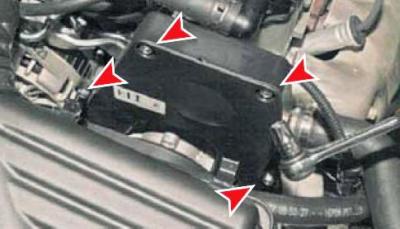
…using a 10 mm socket head, unscrew the four bolts securing the upper front timing belt cover.
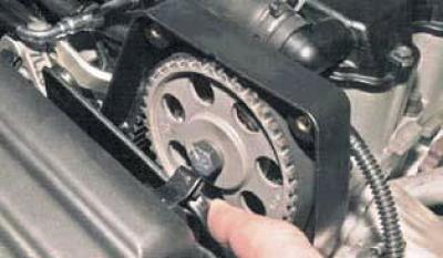
Having moved the front cover away from the back, we check the condition of the belt.
To replace the timing belt, remove the air filter (see Removal the air filter). Remove the right front wheel. Remove the air conditioning compressor drive belt (see Checking the condition and replacing the air conditioning compressor drive belt). Remove the generator drive belt (see Replacing the alternator drive belt). For clarity, we show the operations for replacing the timing belt on a dismantled engine.
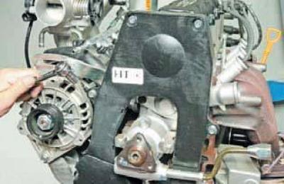
Using a 10 mm socket, unscrew the four bolts securing the upper front timing belt cover…
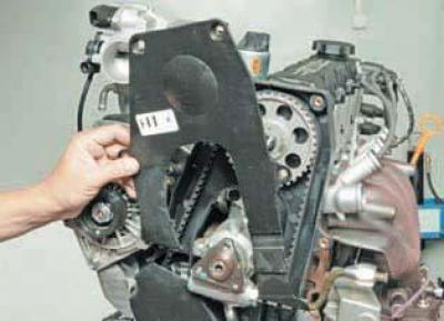
…and remove the lid.
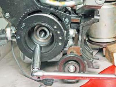
Using a high 17 mm socket, turn the crankshaft clockwise using the auxiliary drive pulley mounting bolt..
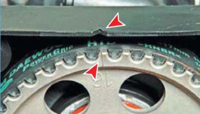
…until the mark on the toothed pulley of the camshaft is aligned with the slot on the rear cover of the timing drive.
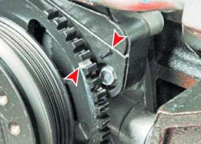
In this case, the mark on the auxiliary drive pulley (located between the 5th and 6th teeth, counted clockwise from the platform without teeth) should be located opposite the pointer on the lower front timing cover.
We dismantle the power steering pump (see Removal the power steering pump).
Using a high 17 mm socket, unscrew the bolt securing the auxiliary drive pulley. To keep the crankshaft from turning, have the assistant engage fifth gear and press the brake pedal.
We take out the bolt with the washer..
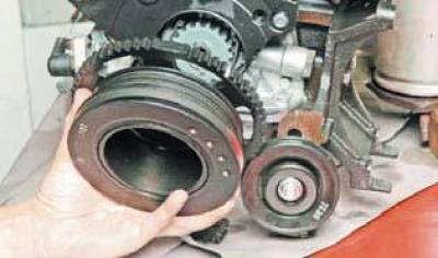
…and remove the auxiliary drive pulley.
Once again, we check the alignment of the timing mark on the toothed pulley of the camshaft with the slot on the rear cover of the timing drive. If the valve timing mechanism phases are set correctly…
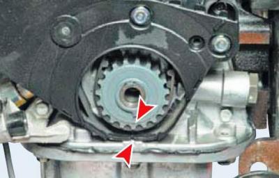
…the mark on the toothed pulley of the crankshaft should be located opposite the slot on the rear cover of the timing drive.
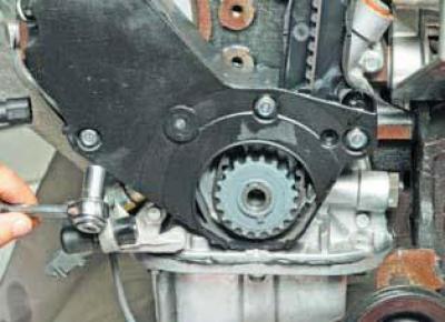
Using a 10 mm socket, unscrew the three bolts securing the lower front timing belt cover…
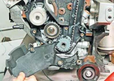
…and remove the lid.
We loosen the tension of the timing belt by turning the spring-loaded movable plate of the tension roller clockwise with a screwdriver until the hole in it is aligned with the hole in the roller bracket..
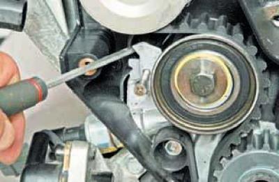
…and insert a pin with a diameter of 4.0–4.5 mm into both holes (for example, a drill shank or a screw).
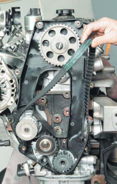
We remove the belt from the toothed pulleys of the camshaft and crankshaft and the coolant pump.
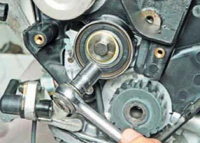
Using a 12 mm socket, unscrew the tension roller mounting bolt…
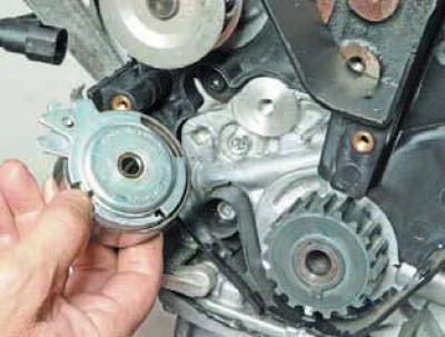
…and we shoot a video.
We install the new roller in the reverse order.
Before installing the accessory drive belt, make sure that the timing marks on the toothed pulleys of the crankshaft and camshaft are aligned with the corresponding slots on the rear timing drive cover. In this position, put the belt on the toothed pulley of the crankshaft. Place the rear branch of the belt behind the tension roller and put the belt on the pulleys of the coolant pump and camshaft, eliminating sagging of the front branch of the belt.
We remove the pin from the holes of the movable bar and the tension roller bracket.
Install the auxiliary drive pulley and tighten its mounting bolt. Turn the crankshaft two turns clockwise by the pulley mounting bolt. If…
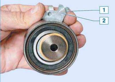
... the pointer 1 of the movable plate of the tension roller is aligned with the recess 2 on the bracket (for clarity, shown on a removed tension roller), then the timing belt tension is normal. If not, we perform additional adjustment of the belt tension by turning the coolant pump.
For this…
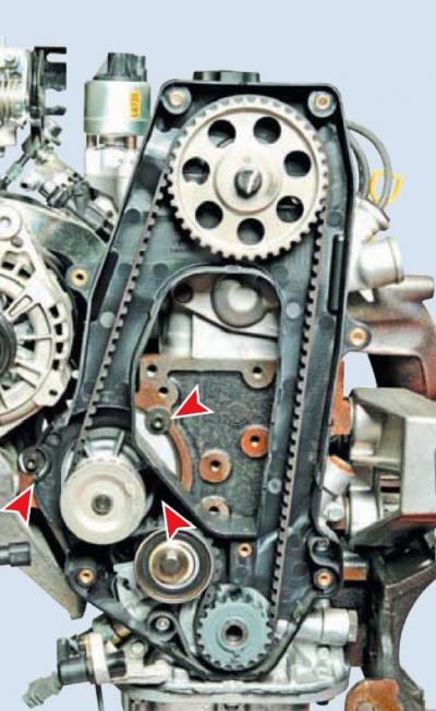
…using a 5 mm Allen key, loosen the three screws securing the coolant pump.
The timing belt tension changes when the pump housing is rotated in the cylinder block socket.
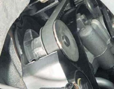
The pump can be turned using the 41 mm hex key on its body.
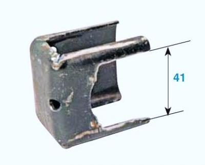
To turn the pump from a metal plate, you can make a device yourself. We install the device in this way..
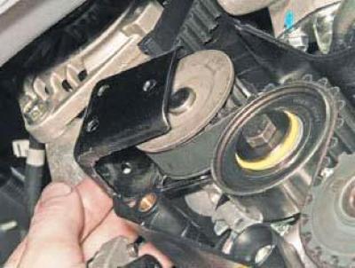
…so that its "paws" tightly grip the hexagon of the pump and we use the device as a lever.
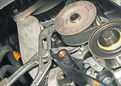
The pump can also be turned by the hexagon using sliding pliers.
Turn the pump counterclockwise until the indicator of the movable plate of the tension roller aligns with the recess on the roller bracket.
In this position, tighten the coolant pump mounting screws. Turn the crankshaft clockwise two turns and check the alignment of the shaft timing marks. Repeat the operation if necessary. Make sure there is no leakage from under the coolant pump. If necessary, replace the pump housing sealing ring (see Fig. Removal the coolant pump).
Further assembly is carried out in reverse order.
Fill the hydraulic drive of the power steering with working fluid and remove air from it. Bring the coolant level to normal.